
Integrated Motors with Built-In Drives: Wiring, Cabinet Space & Cost Benefits (Part 2)
Integrated motors with built-in drives are often summed up as “less wiring, smaller cabinets,” but where exactly the savings come from, how much they are worth, and when the integrated approach does not pay off—these questions rarely get actionable answers. Following the previous installment, this article breaks down the benefits of integrated motors from four angles—architecture, wiring, space and cost, and thermal limits—and provides a cable-estimation framework plus a selection checklist.
From Separate to Built-In: What Changes in the Structure
In the previous installment we analyzed how closed-loop steppers rely on real-time encoder compensation to keep from losing steps; this time the focus shifts to structure—what happens when the closed-loop drive is no longer mounted in the control cabinet but installed directly inside the motor? An integrated motor is exactly the product form that houses the drive and encoder at the rear of the motor (or inside the end bell). Motor, drive, and feedback become one unit, and only the shaft extension plus one or two connectors remain exposed on the machine side.
This integration is far more than simple stacking: the drive board must be redesigned around the motor’s vibration, temperature rise, and sealing conditions. Power and feedback runs that were several meters long shrink to a few centimeters, and long-line reflections, crosstalk, and grounding headaches disappear—the price is that drive-stage heat must now be dissipated through the motor housing.
This structural “move” may look like a mere change of mounting location, but in practice it reshapes the machine’s electrical architecture, wiring scheme, and delivery workflow: part of the commissioning moves upstream to the factory, and the machine builder receives ready-to-install actuator units that work straight out of the box.
Wiring: From Multi-Core Long Cables to a Single Bus
In a conventional setup, every axis needs its own power cable and encoder feedback cable run from the control cabinet. Multi-core shielded cables multiply with the axis count and distance, drag chains grow increasingly crowded, and shield grounding plus power/signal segregation all have to be handled case by case.
An integrated motor typically needs just one power feed plus one communication cable, daisy-chained end to end in a RS485, CANopen, or EtherCAT bus: each motor draws power locally, node addresses are assigned in the commissioning software, and both ends of the link are properly terminated; adding or removing an axis is simply a matter of adding or removing nodes in the chain.
With fewer connectors and less wiring labor, fault finding also becomes methodical: check the bus first—is the link intact, are any messages timing out? Then check the nodes—which station address dropped off, and what errors are reported? Only then does the motor itself come into play. This three-level triage separates line-wide faults from single-axis anomalies.
Dual Savings: Cabinet Space and Cable Cost
Once the drive “moves into” the motor, the most visible change in the cabinet is the freed-up DIN rail. On the balance sheet, it looks like this:
- Smaller cabinets—or none at all: multi-axis machines can replace the traditional control cabinet with a small terminal box, cutting both purchase and floor-space costs;
- Less cable: power and feedback are merged and total run length shrinks—the more dispersed the axes, the bigger the savings;
- Distributed heat load: drive heat is spread over the machine frame along with the motors, making cabinet temperature rise easier to control;
- Faster assembly and service: motors work straight out of the box, replacement is a whole-unit plug-in swap, and downtime is shorter.
A rough framework can put numbers on it: assume a machine with N axes and an average distance L meters from each axis to the cabinet. The conventional scheme needs about N×L of power cable plus N×L of feedback cable—two runs in total—while the bus scheme uses a power trunk plus the daisy-chained bus, with total length close to the sum of the distances between adjacent axes. Take an 8-axis machine with an average 5 m routing: the conventional dual-run approach is on the order of 80 m, whereas an integrated setup can often compress that by an order of magnitude, with wiring hours and drag-chain costs falling in step.
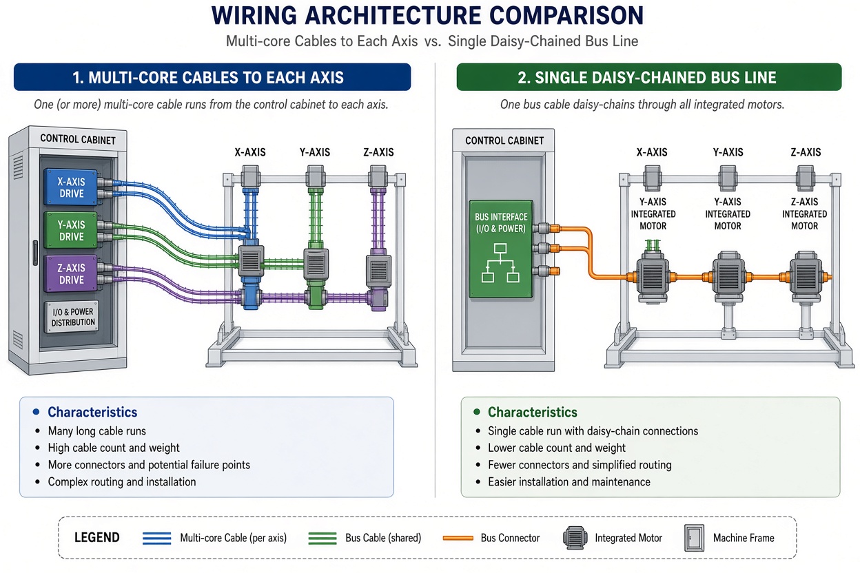
| Aspect | Split solution (drive in cabinet) | Integrated solution (drive built in) |
|---|---|---|
| Wiring per axis | One power cable plus one feedback cable | Power feed plus daisy-chained bus |
| Cabinet space | DIN rail and cooling reserved per axis count | Only controller and power supply remain |
| Expansion and replacement | Add drives in the cabinet and re-route wiring | Add bus nodes and swap whole units |
In addition, with fewer cables inside the drag chain, bend radius and inter-cable interference become easier to manage, improving the long-term reliability of the moving parts.
Which Motion Applications Fit Best
The integrated form factor is best suited to applications with dispersed axes and low-to-medium power per axis: multi-point feeding and sealing-cutting units in packaging machinery, segmented drives along logistics conveyor lines, distributed axes in textile and woodworking machines, and modular special-purpose machines that need fast changeovers. On mobile equipment such as AGVs, a low-voltage integrated solution can even eliminate the onboard control cabinet, further shrinking the whole machine. The more axes there are and the longer the cable runs, the more pronounced the wiring and space benefits described above become.
For a specific machine, run a three-step self-check: count the axes—list every dispersed axis; measure the distance—estimate the cable run from each axis to the control cabinet; check the power—confirm that most axes fall in the low-to-medium current range. Low-voltage solutions commonly use a 24/48 V DC bus, and 220 V AC input ratings are also available. If all three answers point to “many, long, and low-to-medium,” the benefits will generally hold.
Meanwhile, thanks to the built-in encoder closed loop, the motor retains the lost-step immunity described in the previous installment even under sudden load changes—an advantage that is in no way diminished by the structural integration.
Engineering Limits: Heat, Load, and Trade-offs
The limits deserve an objective look as well: a built-in drive means the motor has to handle its heat too. Drive-stage losses stack onto the motor’s own, so winding temperature rise is tighter than in a split solution. Motor windings are typically built with Class F insulation, and temperature-rise limits are commonly verified by the resistance method against Class B (80 K) or Class F (105 K) values, subject to the applicable product standard; sizing should leave margin for load factor and ambient temperature.
For applications with sustained heavy loads, high ambient temperatures, or highly dynamic, frequent start-stops, a split solution is still worth evaluating—placing the drive back in the cabinet to take advantage of forced airflow. For applications with extremely demanding dynamics, integrated and split architectures are complementary rather than substitutes.
Three Selection Questions and a Summary
To decide whether integrated motors make sense for you, start with three questions: Are the axes dispersed? Is there any cabinet space left? Does the site value clean wiring more than ultimate performance? If the answers lean toward “dispersed, cramped, and simplicity first,” the integrated solution usually delivers a shorter assembly cycle and lower total cost.
In short: the essence of the integrated motor is trading “cabinet space and long cables” for “a small volume at the rear of the motor plus one bus cable.” As long as the axes are dispersed, power is low-to-medium, and heat is manageable, that trade pays off in most cases.
FAQ
Q: With the drive built in, does a motor fault mean replacing the whole unit?
A: A whole-unit plug-in swap is indeed the fastest fix on site. Still, before replacing anything, run the three-step triage—“bus, node, motor”—to confirm the fault is in the motor itself; on the repair bench, the drive board and the motor can be tested separately.
Q: Won’t a built-in drive make the motor run hotter?
A: Drive losses are indeed added to the motor’s own heat, but the thermal design covers the complete operating conditions. If the motor is sized against load factor and ambient temperature and the mounting surface fits flush, temperature rise generally stays within limits.
Q: How do I choose between RS485, CANopen, and EtherCAT?
A: RS485 suits point-to-point positioning at low-to-medium speeds with a modest axis count; CANopen is common in mobile equipment and low-voltage settings; EtherCAT fits production lines with many axes and strict synchronization requirements. A single bus link should use a single protocol.
Previous Installments
If you are new to this series, start with the previous installment, “Why Closed-Loop Steppers Don’t Lose Steps,” to fill in the fundamentals of encoder-based closed-loop control first.
You may also explore HFY DRIVE’s series of closed-loop stepper drives. Their drive technology shares the same roots as our integrated motors, making them a useful reference for split-architecture solutions.