EMC in Practice: Interference Sources and Countermeasures
On the bench everything works. Put the drive in the cabinet, though, and it occasionally loses steps, drops communication, or throws false alarms. Most of the time the drive itself is fine; the electromagnetic compatibility (EMC) design is what’s wrong. This article covers where on-site interference comes from, practical rules for shield grounding, filtering, and cable separation, and a five-step troubleshooting sequence.
On-Site Interference Sources: First Work Out Who’s Interfering with Whom
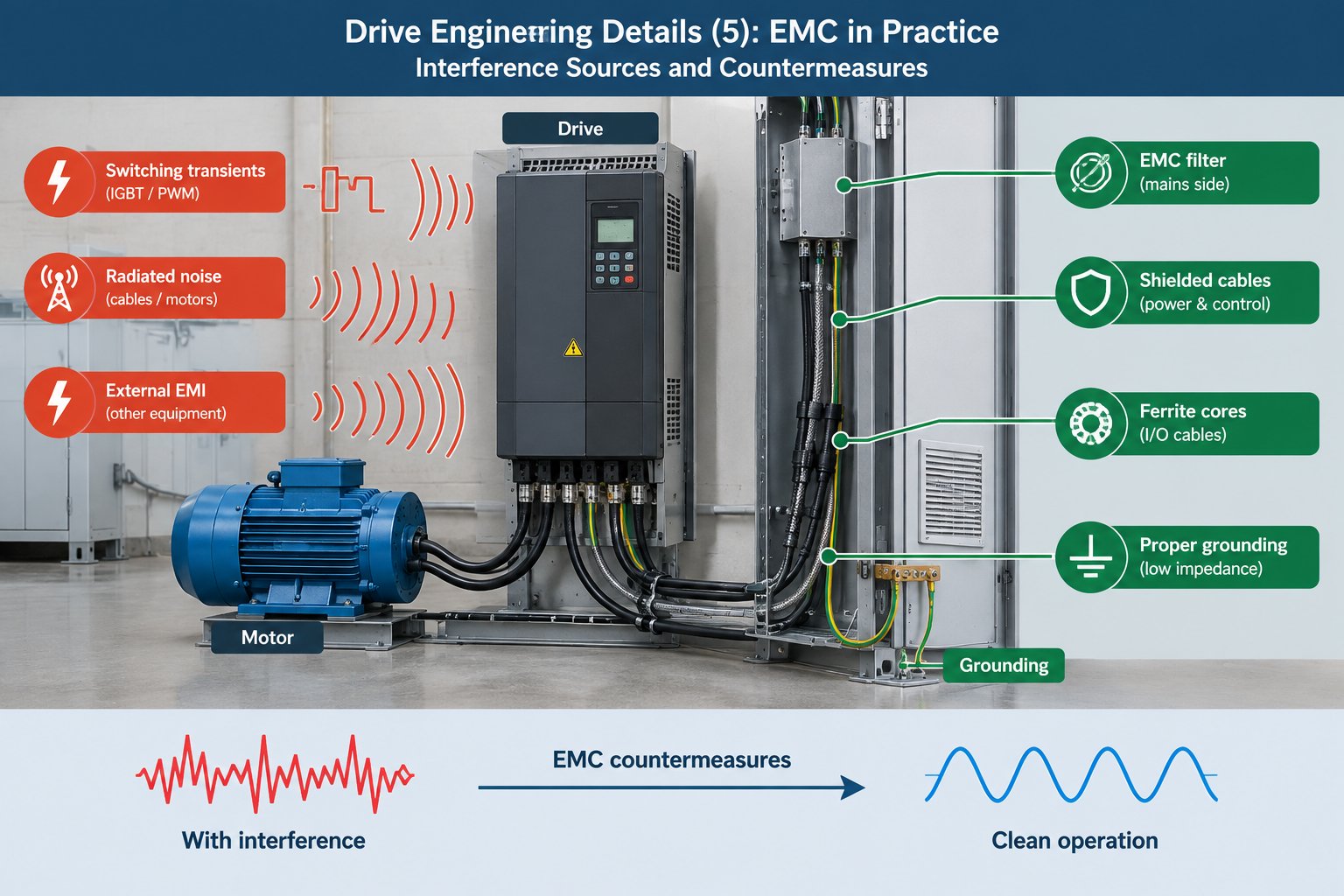
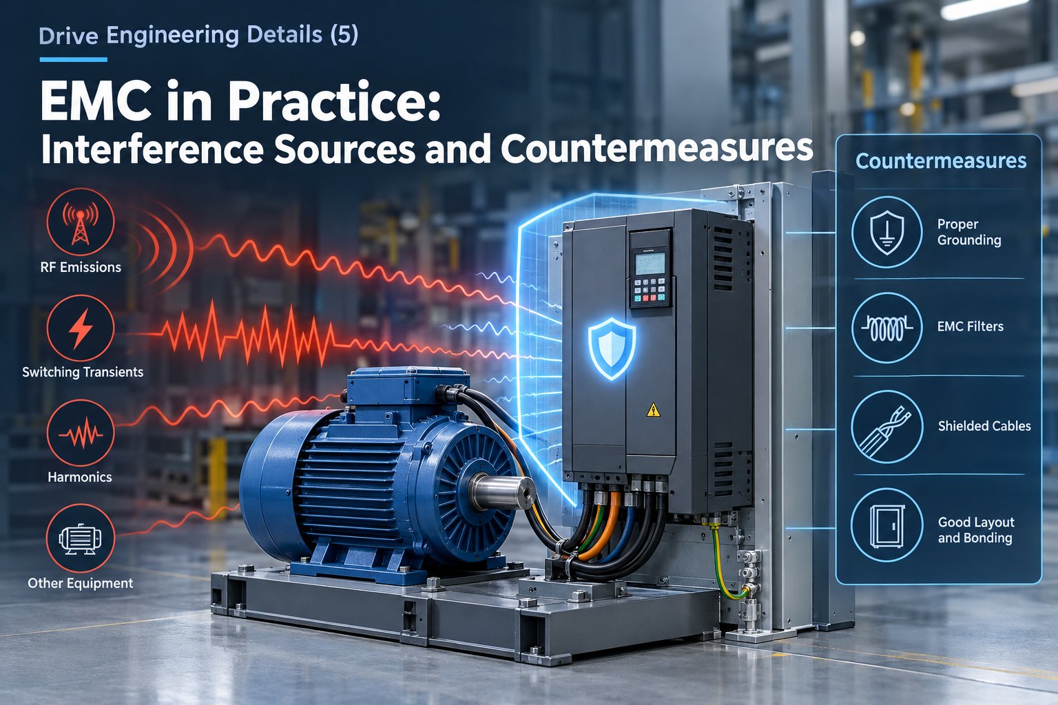
Nearly all of the interference energy on site comes from fast switching in the power stage. The power transistors in a stepper/servo drive switch tens of thousands of times per second, and the resulting high dv/dt and di/dt “leak” outward through common-mode capacitance, shared ground conductors, and parasitic coupling between cables. On top of that you get rectifier and switching noise from VFDs in adjacent cabinets, arcing when contactor contacts open, back-EMF when DC coils are de-energized, plus electrostatic discharge and RF sources. Together these form the electromagnetic environment of an industrial site.
For interference to turn into a fault, three elements must all be present: an interference source, a coupling path, and a susceptible circuit. Of the three, the coupling path is the one engineers can control most easily. By mechanism there are four types: conducted coupling arriving along power lines; capacitive coupling between long parallel cable runs, where high-impedance analog signals are most vulnerable; inductive coupling where high-current loops link with signal loops and disturb pulses and low-level signals; and spatial radiated coupling. Troubleshooting starts with three questions: Is the fault synchronized with a particular device starting or stopping? Is it synchronized with motor acceleration and deceleration? Does it change when cables are moved or the cabinet door is opened and closed? The answers point directly at the coupling type.
Shielding and Grounding: Single-Point Grounding and 360° Bonding
A shield only works if it is grounded properly. The general practice: ground the shields of low-frequency and analog signal lines (±10V command, analog feedback, temperature sensing) at one end only, so a potential difference between the two ends can’t drive a ground loop. Bond the shields of power cables (motor leads, braking resistor lines) at both ends with 360° contact, clamping the shield circumferentially to the metal mounting plate with metal cable clamps or EMC glands. Whatever you do, don’t twist the shield into a “pigtail” and land it on a terminal. Above a few tens of MHz, a pigtail is effectively an open circuit.
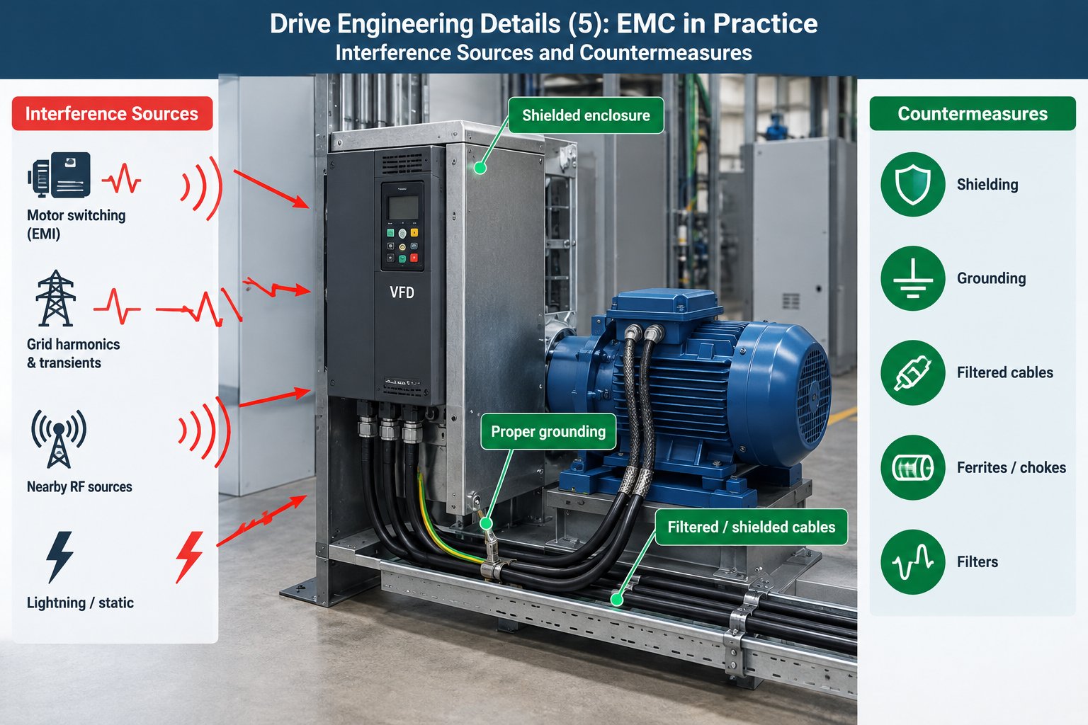
Then three grounding rules. Run the protective earth (PE) separately from the signal ground (0V) and converge them at a single point on the cabinet grounding busbar. Keep ground paths short and wide: paint on the mounting plate’s contact surfaces must be removed or pierce-type washers fitted, because relying on screws to carry current “incidentally” is a common failure point at high frequencies. Avoid ground loops as well. A potential difference between two ground points drives common-mode current along the shield, which is exactly why haphazard double-ended shield grounding can make things worse. It’s the same story as airflow paths and heatsink clearances: the placement of the grounding busbar, filters, and segregated cable-duct zones is a detail that is very hard to rework once installed.
Filtering and Cable Separation: Zoning Power and Signal Wiring
Install the power line filter as close to the drive’s power input as possible, with its metal case in broad contact with the bare metal of the mounting plate. The most common mistake is bundling or co-routing the filter’s input and output lines. Do that and high-frequency interference bypasses the filter, couples straight into the output side, and the filter might as well not be there. Suppress noise at the source too: connect surge suppression components across contactor and relay coils (RC snubbers for AC circuits, freewheeling diodes for DC circuits) to cut off the most typical class of pulse interference.
Separate the wiring by “energy level”: route power lines, signal lines, and communication lines in separate runs, starting from 20–30 cm of spacing. Where space is tight, use compartmentalized cable ducts with metal dividers. When a crossing is unavoidable, cross at right angles and avoid long parallel runs. In-cabinet zoning can follow the table below:
| Cable Category | Typical Examples | Key Routing Points |
|---|---|---|
| Power lines | U/V/W motor leads, braking resistor lines | Shielded cable; shield bonded 360° at both ends; dedicated cable duct level |
| Signal lines | Pulse/direction, analog, encoder lines | Shielded twisted pair; shield grounded at one end; at least 20 cm from power lines |
| Communication lines | RS485, CANopen, EtherCAT | Dedicated shielded twisted pair in the communication level; shield handled per the bus specification |
Five-Step Troubleshooting: From Symptom to Root Cause
The biggest pitfall in EMC remediation is changing five things at once. Even if the fault goes away, you can’t tell which measure actually fixed it. Proceed in a fixed order and keep records at every step:
- Reproduce and log: note when faults occur, how often, and which equipment was operating at the time;
- Isolate variables: pause suspected interference sources one by one (the VFD in the adjacent cabinet, for example) and verify the correlation;
- Ground first, then cables, then filters: check grounding continuity and shield bonding first, then wiring spacing, and only then consider adding or replacing filters;
- One change at a time: modify only one thing per round and retest fully, so the result can be attributed;
- Standardize what works: write verified fixes into the cabinet assembly checklist so the same trap doesn’t get hit twice.
▲ Knowledge map of this article
In practice, most on-site problems are found at step two or three. If you suspect the sensitive link is on the drive side, compare performance across input types: switch from open-collector pulses to differential line-driver signals, or move straight to a closed-loop drive with encoder feedback. Differential interfaces offer noticeably stronger common-mode noise rejection, which makes them worth considering when you’re upgrading multi-axis equipment.
Standards Quick Reference
- IEC 61800-3 (EMC of power drive systems): categories C1 (first environment, unrestricted) / C2 (first environment, professional installation) / C3–C4 (industrial second environment) — match the drive’s declared category to your site before choosing filters.
To put any of this to work, HFY DRIVE’s closed-loop stepper drivers are a sensible starting point for your next project.