Three Structures, Torque-Angle Curve & Holding Torque
This article separates variable reluctance, permanent magnet, and hybrid constructions, then traces the torque-angle curve back to where it comes from. By the end you should be able to read that sinusoid and see a lost step for what it really is — a boundary crossing.
1. Three Constructions: Where the Torque Comes From
Acarnley’s classic textbook sorts stepper motors into three types according to how torque is produced. The split determines torque output, step angle resolution, and cost, so it’s the first key to reading any motor selection table.
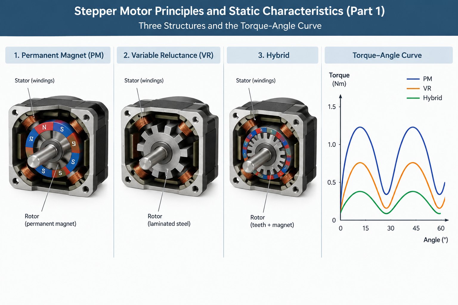
Variable reluctance (VR): both stator and rotor are slotted silicon-steel laminations with no permanent magnets at all. Torque is produced purely by the reluctance torque that arises as the stator and rotor teeth shift relative to one another. The magnetic circuit always seeks minimum reluctance, so the tooth-aligned positions become the rotor’s comfort zone. Construction is simple and cheap; the price you pay is low torque density (torque available per unit volume).
Permanent magnet (PM): here the rotor is itself a permanent magnet. It supplies the main field and aligns with the field of the energized stator windings, which yields higher torque. The problem is that this kind of rotor cannot carry many poles, so the step angle (the angle the rotor turns through each time a pulse arrives and the winding energization state changes) tends to be large.
| Type | Torque Source | Advantages | Limitations |
|---|---|---|---|
| Variable reluctance (VR) | Reluctance torque from changing tooth-slot reluctance | No permanent magnets, low cost | Low torque density |
| Permanent magnet (PM) | Main field from the rotor’s permanent magnets | High torque | Large step angle |
| Hybrid (HB) | Permanent-magnet field plus fine-tooth reluctance variation | Combines high torque with fine step angle | Most complex construction |
2. Hybrid Construction: Where the 1.8° Industry Standard Comes From
Hybrid (HB) motors combine the strengths of both families. At the center of the rotor sits a ring-shaped permanent magnet magnetized axially (flux lines run along the shaft); it provides the main field and contributes PM-grade torque. The small teeth machined at both ends of the rotor take over the fine tooth pitch of VR designs, so you get PM torque together with VR’s fine tooth pitch.
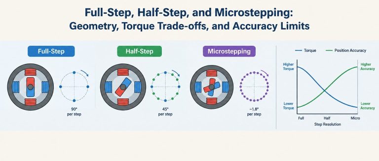
Resolution rises accordingly. A typical hybrid rotor carries 50 milled teeth, so the tooth pitch (the angular spacing between adjacent teeth) works out to 360° ÷ 50 = 7.2°. The two phase windings are energized through four states in sequence, the scheme commonly known as the four-step or full-step sequence, and each state advances the rotor by 1/4 of a tooth pitch, i.e. 1.8°, for exactly 200 steps per revolution. This is how 1.8° (200 steps/rev) became the industry standard that persists to this day.
3. Why a Fine Tooth Pitch Improves Resolution
Strip the numbers away and the picture is simple: any position where a rotor pole aligns with a stator tooth is a stable equilibrium point, and nudge the rotor from one, it returns on its own. The more tooth pitches fit within one revolution, the denser these equilibrium points become. The density of tooth-alignment equilibrium points is set by the tooth pitch, so the finer the pitch, the higher the base resolution.
The excitation scheme then subdivides within each tooth pitch: the four-step sequence above cuts one tooth pitch into 4 equilibrium points. So if you want to judge a motor’s fundamental capability, look at the rotor tooth count first. Everything the drive does afterwards happens inside this framework of equilibrium points.
4. Torque-Angle Characteristic: Where Holding Torque Comes From
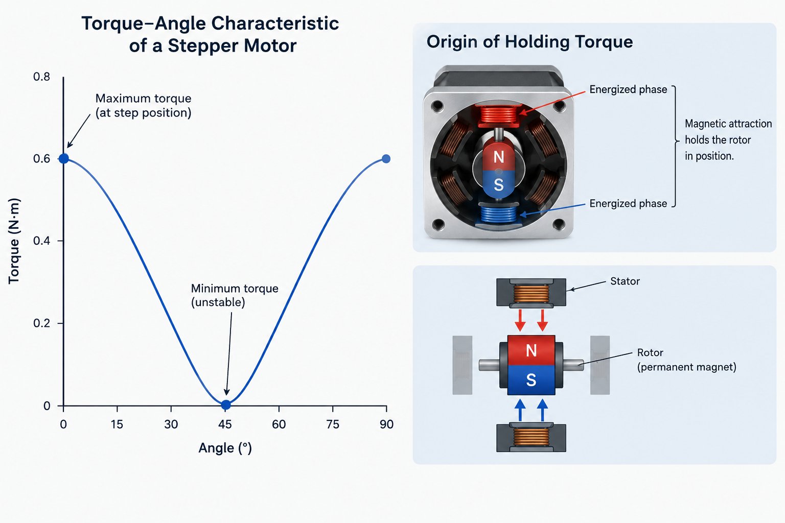
Hold the rotor and let it deviate from its equilibrium position by a small angle, then watch how the static torque changes. That curve is the torque-angle characteristic. The deviation is called the load angle and is measured in electrical degrees: each tooth pitch the rotor travels corresponds to 360 electrical degrees.
The physical picture is intuitive. At zero load angle the teeth are perfectly aligned, the reluctance of the magnetic circuit is at its minimum, and the magnetic pull cancels out in all directions, so net torque is zero. That is exactly the stable equilibrium point. Once the rotor deviates, the magnetic circuit tries to return to the minimum-reluctance position; the restoring torque grows with the deviation and peaks at roughly 90 electrical degrees.
The entire curve is closely approximated by T=−T max·sin(θe), where θe is the load angle; the negative sign means the torque always points back toward equilibrium. The peak of the curve, T max, is the holding torque, i.e. the maximum external torque the motor can withstand while energized at rated current with the rotor held stationary.
5. Static Stability Region: A Lost Step Is a Boundary Crossing
The restoring torque can pull the rotor back only under one condition: the load angle has not left the static stability region. When a load disturbance pushes the rotor away from its equilibrium point, the magnetic pull brings it back as long as it has not crossed the midpoint between adjacent equilibrium points. That midpoint sits roughly ±half a tooth pitch away: ±180 electrical degrees, i.e. ±3.6°, or ±two full steps on a 1.8° motor.
Once that midpoint is crossed, the rotor slides along the magnetic pull into the next equilibrium point, and its actual position ends up a whole tooth pitch (four full steps) away from the position commanded by the drive. This is a lost step. A lost step is not a vague symptom of “insufficient torque”; it is a definite crossing of a boundary.
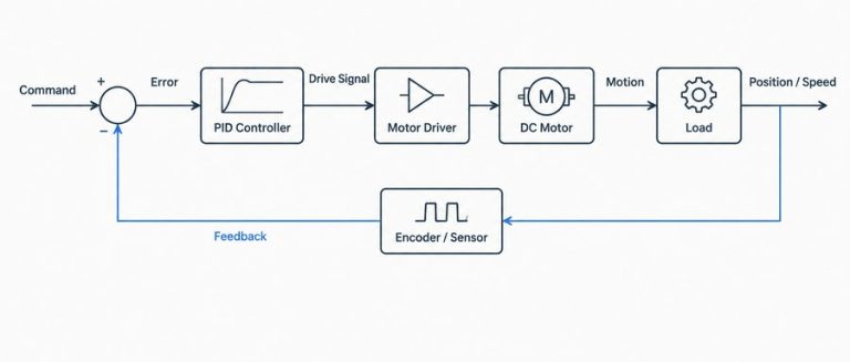
The engineering takeaway, in practice: keep the load torque clearly below the holding torque (a common rule is to leave a margin of 50% or more) and verify the torque-angle characteristic under worst-case conditions. In applications where lost steps cannot be tolerated, add an encoder to form a closed loop and let the drive correct the position error in real time.
Summary
- Torque production comes in three types: VR relies on reluctance variation, PM on the rotor’s permanent-magnet field, and HB combines both.
- Tooth pitch sets the density of stable equilibrium points: 50 teeth with four-step excitation give 1.8° and 200 steps/rev.
- The torque-angle characteristic is T=−T max·sin(θe), and its peak is the holding torque.
- The static stability region ends at the midpoint between adjacent equilibrium points; cross that midpoint and you have lost a step.
▲ Knowledge map of this article
If lost steps are a problem in your project right now, have a look at HFY DRIVE’s closed-loop stepper drivers, which use encoder feedback to correct every boundary crossing in real time.