Electronic Commutation and Power Stages in Brushless Motors
Motor & Drive Basics Part 2: Electronic Commutation and Power Stages in Brushless Motors
Take the carbon brushes out of a motor and the commutation problem doesn’t go away. Somebody still has to do the switching. This part explains how that works: what actually separates BLDC from PMSM, how Hall commutation differs from FOC, and why the three-phase inverter bridge, PWM, dead time, and freewheeling are each there for a reason.
From Mechanical to Electronic Commutation: Where Did the Commutator Go?
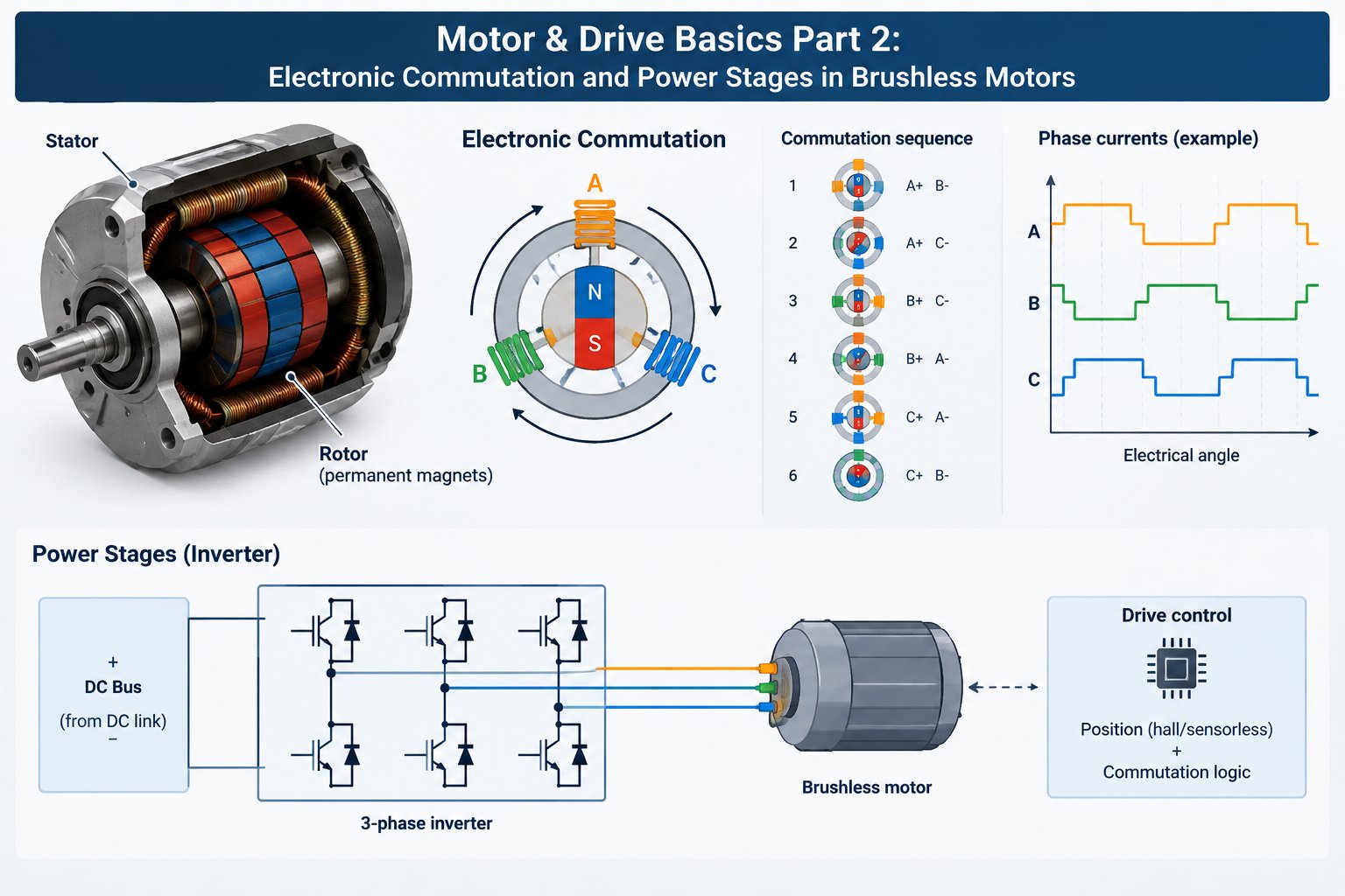
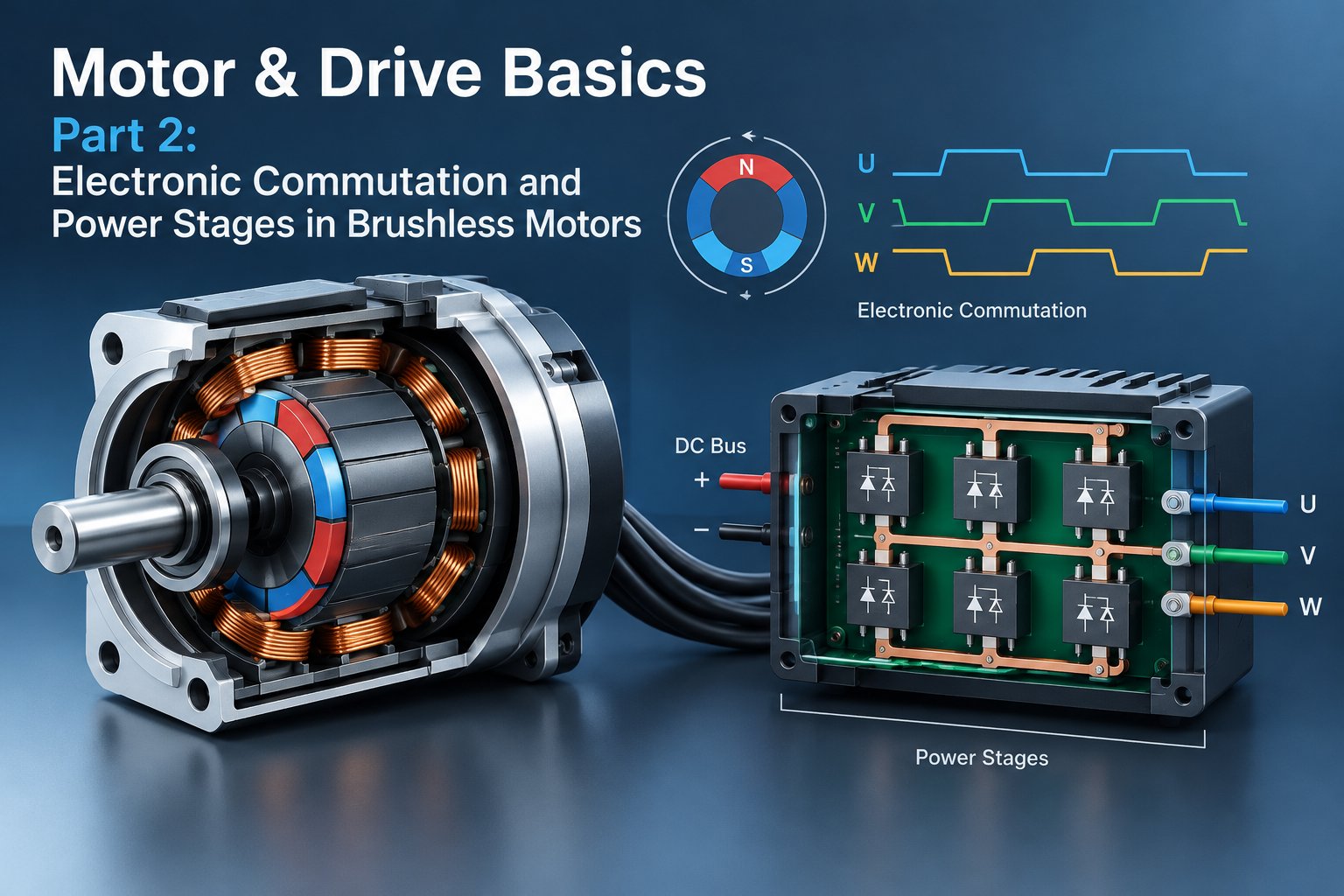
A brushed motor does the phase switching mechanically: carbon brushes riding on the commutator energize the windings in turn as the rotor spins. A brushless motor moves that job into the drive, where power switches energize the windings in sequence according to rotor position. This is electronic commutation.
Here’s the part that surprises anyone coming from brushed motors: the brushless motor itself is nothing more than “a permanent-magnet rotor plus polyphase stator windings.” It cannot commutate on its own, and it will not spin just because power is applied—the entire commutation task falls to the drive.
And before the drive can switch anything, it has to know where the rotor is. That requirement is what gives you the two mainstream routes: Hall commutation and FOC.
BLDC vs. PMSM: How Two Close Relatives Differ
Structurally the two are identical: a permanent-magnet rotor with a three-phase stator. The real divide lies in the waveform of the back-EMF, the voltage induced in the windings as the rotor turns.
A BLDC motor has a near-trapezoidal back-EMF and is conventionally paired with square-wave drive; a PMSM has a near-sinusoidal back-EMF and is conventionally paired with sinusoidal drive. Match the drive waveform to the back-EMF and the system runs smoothly.
| Aspect | BLDC (square-wave camp) | PMSM (sinusoidal camp) |
|---|---|---|
| Back-EMF waveform | Near-trapezoidal | Near-sinusoidal |
| Typical drive method | Six-step square wave | Sinusoidal / FOC |
| Torque smoothness | Torque ripple at commutation | Smooth and quiet |
| Typical applications | Fans, pumps, e-bikes, power tools | Servo systems, joint modules, precision motion |
Hall Commutation vs. FOC: The Difference in One Sentence
Hall commutation: three Hall sensors (tiny position switches that sense magnetic polarity and output logic-level signals) are mounted on the stator. Like mileposts, they report which sector the magnetic poles have reached, and the drive switches phases accordingly. That’s the whole job: it only answers “which winding should be energized now.”
FOC (field-oriented control) in one sentence: the rotor field angle is computed in real time, and the stator current is decomposed into a field component and a torque component that are regulated independently, so the stator field always pulls the rotor at the optimal angle.
Hall commutation is discrete switching logic that changes phase at fixed points; FOC is vector computation with continuous current control. Hall hardware is cheap and rugged. FOC costs more processing, and in return you get smooth, efficient running.
Square Wave vs. Sine: The Divide Between Noise and Smoothness
Square-wave (six-step) drive energizes entire phases and switches them in blocks. Control stays simple and switching losses stay low. The trade-off shows up at the shaft: torque steps at every commutation instant, low-speed rotation feels jerky, and the electromagnetic noise is more noticeable.
Sinusoidal drive makes the three-phase currents vary continuously in a sine pattern, so torque comes out smooth and the motor runs quiet. The cost is higher demands on computing power and current sampling. For fans and pumps, square wave is enough; gimbals and precision pumping cannot do without sine.
The Three-Phase Inverter Bridge: Six Switches as the Universal Platform
The smallest unit is the half-bridge: one high-side switch in series with one low-side switch, with the midpoint brought out to the load. Two half-bridges form a full bridge (an H-bridge), which can run a brushed DC motor in both directions. Three half-bridges in parallel make up the three-phase inverter bridge, the universal platform of brushless drives.
Its switching discipline comes down to a single rule: on any leg, only one of the high-side and low-side switches may conduct at any given moment. Break it and you get shoot-through, which we’ll come back to under dead time.
Under the direction of rotor position and the control algorithm, the six switches open and close in turn, chopping the DC bus voltage and distributing it across three phases. Every commutation event comes down to some on/off combination of those six switches.
PWM Chopping: The “Faucet” for Adjusting Voltage and Current
PWM (pulse-width modulation): the switches turn on and off rapidly at a fixed frequency, and the fraction of time they conduct, the duty cycle, equivalently controls the average voltage. Think of tapping a faucet quickly: the longer the valve stays open, the greater the flow.
Raise the duty cycle and the average voltage and winding current rise with it, so torque grows. A closed-loop drive goes a step further: it samples current in real time and corrects the duty cycle, pinning the current near its target. Whether you call that regulating voltage or regulating current, underneath it is the same chopping action.
Dead Time and Freewheeling: Two Safeguards You Cannot Skip
Dead time: at the moment the high-side and low-side switches hand over, a gap of a few microseconds is inserted during which both are off. That gap prevents shoot-through, one device not yet turned off while the other is already on, short-circuiting the bus. On the shop floor, this is the most common cause of destroyed power stages.
Freewheeling: a winding is an inductor, and inductor current cannot change instantaneously. Once a switch turns off, the current must be released through a freewheeling diode (or a synchronous-rectification path); otherwise the high-voltage spike induced by the inductance will break down the devices.
Dead time prevents short circuits; freewheeling vents stored energy. Neither can be omitted. Hughes’ Electric Motors and Drives returns to this point repeatedly in its brushless and drives chapters. Reliability hides in exactly these switching details.
That closes out the drive’s low-level “world of switches.” The inverter bridge takes care of commutation and PWM takes care of magnitude; dead time and freewheeling are there purely to keep the hardware alive.
▲ Knowledge map of this article
If you want to see products where “the drive handles commutation and control from start to finish,” have a look at HFY DRIVE’s closed-loop stepper drivers.