Feedback, Servo Loops, and Reading Motor Datasheets
This article answers two questions that come up on almost every project: how does the drive know where the rotor is, and how precisely can it stop? And how do you read the curves and figures in a datasheet without getting misled? By the end you should have three criteria for choosing position feedback, the correct tuning order for the three servo loops, and a way to read datasheets that doesn’t walk you into traps.
1. Three Tiers of Position Feedback: Know Where the Rotor Is First
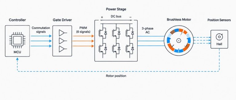
Precise position control has one prerequisite: the drive has to know at all times where the rotor is and which way it is turning. In practice that job falls to three tiers of feedback devices, and accuracy and cost climb with each tier.
- Hall UVW: three signals that step roughly once every 60 electrical degrees. That’s coarse position only, good enough for commutation and no good for precise positioning.
- Incremental encoder: the A and B pulse channels sit 90° out of phase, and whichever channel leads tells you the direction of rotation. Count every edge of both channels and you get line count × 4 counts per revolution, which is standard quadrature decoding.
- It also puts out one Z (index) pulse per revolution as a homing reference, so you can re-establish the zero datum. The reference is lost on power-off, though, and the axis must be re-homed at every power-up.
- Absolute encoder: position survives power loss. Single-turn types remember the angle within one revolution; multi-turn types keep count of full revolutions via a backup battery or a mechanical gear train. That’s what you want where the load may still move after power-off.
2. Choosing an Encoder: Three Checks
So how do you choose among the three? Check three things:
- Resolution: match it to your positioning accuracy requirement, then use the electronic gear ratio (the conversion factor that scales host command increments to the motor’s smallest position step) to line up the resolutions at both ends. Higher is not automatically better.
- Interface match: incremental, SSI (a clock-synchronized serial interface that reads out absolute values bit by bit), or a fieldbus (EtherCAT, CANopen, RS485). The encoder has to be compatible with both the drive and the host controller, end to end.
- Environment: pick shock-resistant construction for high-vibration equipment. Where the encoder sits near a heat source, verify the allowable temperature, and in dusty or oily conditions step up the IP protection rating.
3. The Three Servo Loops, From the Inside Out
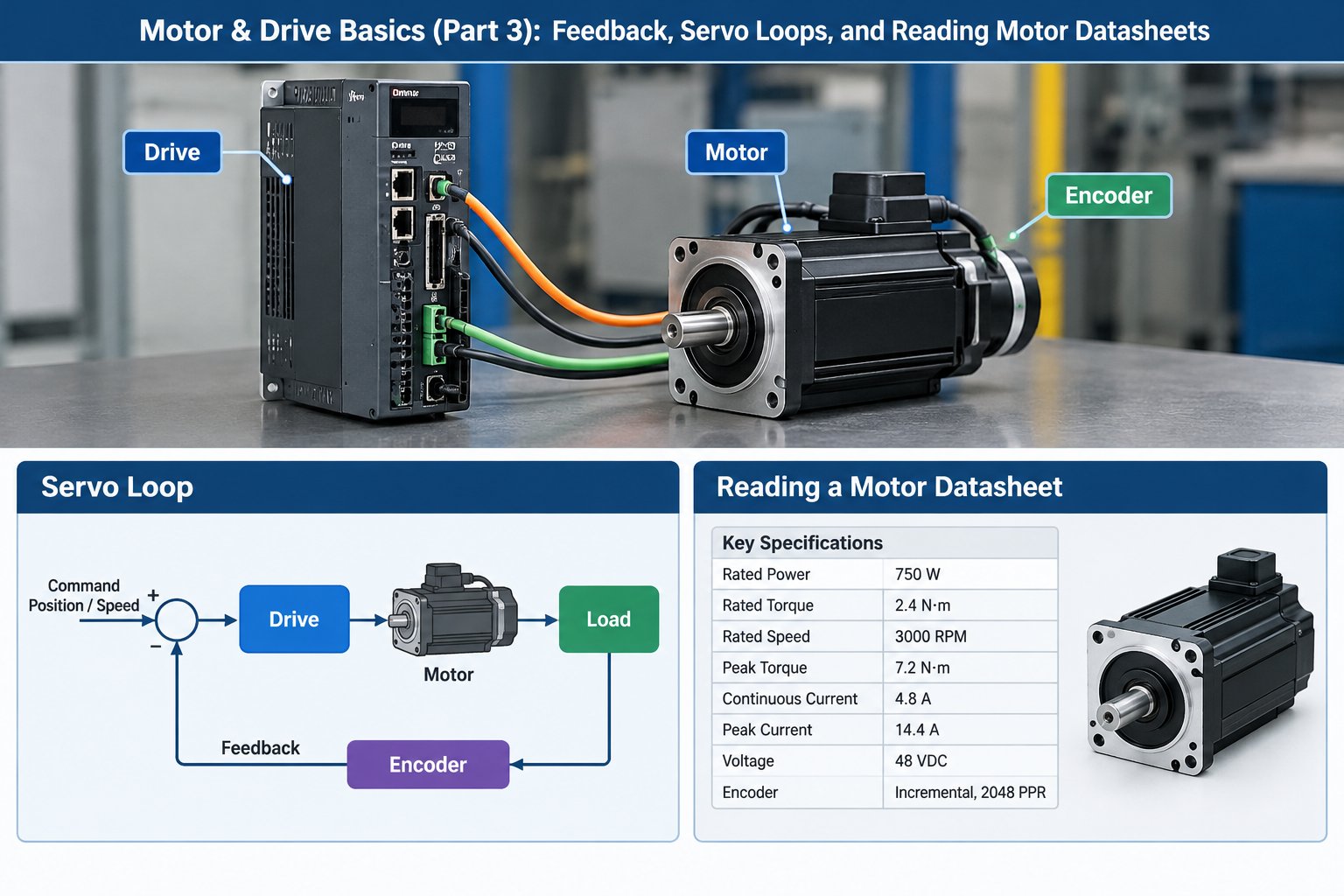
A closed-loop servo nests three controllers. From the inside out: current loop, velocity loop, position loop. The output of each outer loop is the setpoint for the loop inside it, so every layer takes its orders from the one above and manages its own segment.
The current loop sits innermost with the highest bandwidth of the three (the command frequency it can track), kilohertz-class. Its job is keeping winding current tightly on its command, and current means torque. It also enforces the current limit, which is what protects the six power transistors of the three-phase inverter bridge.
The velocity loop sits in the middle with bandwidth in the hundreds of hertz. It decides how smoothly speed tracks its command and how strongly the axis rejects load disturbances. The position loop is outermost: it converts position error into a velocity command for the velocity loop, and it’s what determines final positioning accuracy.
4. The Tuning Order: Current Loop First, Position Loop Last
For tuning there’s one rule and no exceptions: tune the current loop first, then the velocity gain, and the position gain last. Inner loops are the foundation of the outer ones. If an inner loop is unstable, no amount of aggressive outer-loop tuning will hold the system steady.
| Gain Setting | Typical Symptoms | Corrective Action |
|---|---|---|
| Too high | High-frequency whining, oscillation, motor heating | Reduce the gain until oscillation disappears, then back off further for margin |
| Too low | Sluggish response, tracking lag, long settling time | Raise the gain until you approach the onset of whining, then back off |
The rule of thumb on the shop floor: “too high sings, too low drags.” Listening for sound and feeling for temperature rise are the cheapest tuning instruments you’ll ever have.
5. Reading the Datasheet: Hard Specs vs. Conditional Specs
Datasheet ratings come in two kinds. Hard specs hold unconditionally: holding torque (the maximum static torque available at standstill while energized), rated current, insulation class (the thermal rating of the winding insulation), and IP rating (dust and moisture protection). You can compare these directly across products.
Conditional specs require checking the test conditions first. The torque–speed curve depends on the stated supply voltage, current, and drive method; change the conditions and the curve changes. Temperature-rise data likewise depends on mounting and cooling. Read the footnotes before the numbers.
6. The Two Selection Mistakes I See Most Often
- Sizing from a high-speed torque point: the torque–speed curve falls as speed rises, and torque at the high-speed end is often well below the low-speed value. Always verify against the point that corresponds to your actual operating speed and leave ample margin.
- Ignoring the temperature-rise assumptions: curves are typically plotted from cold-state, short-duration tests. Run long enough with poor cooling and the windings heat up, available torque shrinks, and over-temperature protection may even trip. Re-verify under the worst-case cooling conditions.
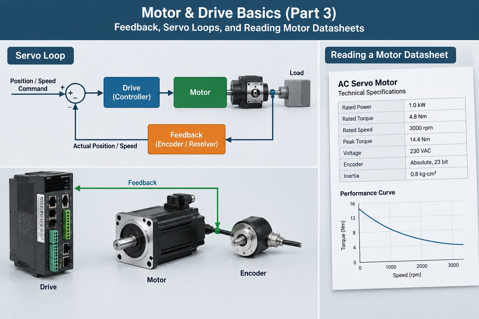
▲ Knowledge map of this article
Avoid these two and your selection is mostly on solid ground. If you want to put feedback, the three loops, and datasheet reading to work on a real product, take a look at our closed-loop stepper drivers.