
Drive Solutions by Industry (Part 2): High-Precision Drives for 3C and Laser Equipment
Drive Solutions by Industry (Part 2): High-Precision Drives for 3C and Laser Equipment
3C electronics and laser equipment place far higher demands on positioning resolution and trajectory smoothness than general handling and conveying applications. This installment focuses on three key points: the true relationship between microstepping and accuracy, smoothness of micro-step motion, and vibration control—providing worked conversion examples, a selection procedure, and a troubleshooting sequence that equipment engineers and purchasing decision-makers can apply directly.
Microstepping vs. Accuracy: Microstepping Provides Resolution, Not Accuracy
The previous installment looked at drive configuration for multi-axis coordination and high-frequency start-stop duty; this one zooms in on single-axis quality. A typical two-phase hybrid stepper motor has a full step angle of 1.8°, or 200 steps per revolution. With the driver set to 10 microsteps, that yields 2,000 microsteps per revolution in theory—a resolution of 0.18°. As a further example, take a directly coupled lead screw: with a 5 mm lead and 16 microsteps, there are 3,200 pulses per revolution, so each pulse corresponds to roughly 5 ÷ 3200 ≈ 1.6 μm—note that this is only the theoretical displacement equivalent.
Actual positioning accuracy is further affected by the motor’s inherent step angle error (usually expressed as a percentage of the full step), the linearity of the microstep current, the load-induced lag angle, and mechanical errors such as lead screw pitch error, backlash, and deflection under load. On most 3C and laser equipment, mechanical drivetrain error often exceeds the theoretical improvement microstepping can offer—get the lead screw, coupling, and preload right first, then talk about raising the microstep count.
A practical route: work backward from the process to define the required resolution—for example, dispensing dot pitch or laser spot step size—then allocate it across lead × gear ratio × microsteps. Avoid using extremely high microstepping to mask mechanical defects.
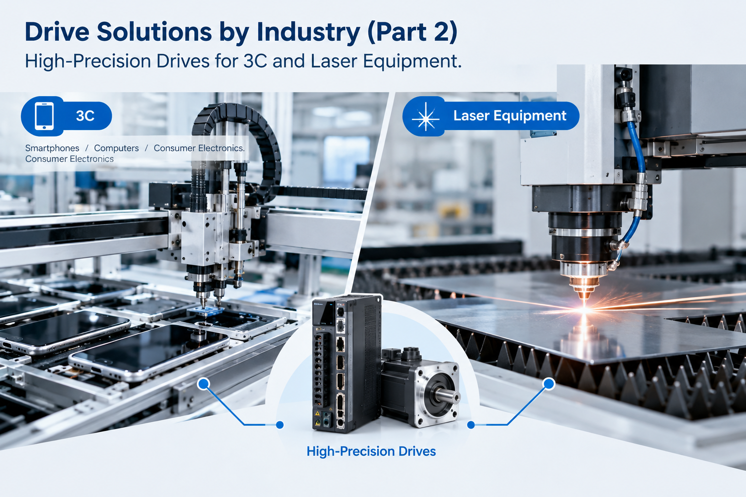
Smoothness of Micro-Step Motion: Why Low-Speed Feeding Feels Rough
Whether microsteps run smoothly depends on the quality of the driver’s current-vector control. Open-loop steppers are prone to speed fluctuation at low speeds, showing up as stick-slip and jerky feeding: uneven shading in laser fill engraving, and inconsistent bead width in dispensing. It must be stressed that a high microstep count does not equal smoothness—current-control resolution and phase linearity are what matter.
Next, run the pulse-frequency numbers: with a 5 mm lead and a required feed of 30 mm/s, the motor speed is 360 r/min. At 16 microsteps the pulse frequency is about 200 × 16 × 360 ÷ 60 ≈ 19.2 kHz, and both the controller’s output rate and the driver’s input limit must cover it. Dropping to 4 microsteps brings the frequency down to roughly 4.8 kHz, at the cost of a coarser waveform and reduced smoothness. Pulse frequency, microstep count, and smoothness must be weighed together.
How to improve: use a gear ratio to move the typical operating speed into the smooth mid-speed band and away from the low-speed stick-slip zone. For axes where smoothness is critical, choose closed-loop steppers with encoder feedback—the current loop corrects in real time against the rotor’s actual position, and low-speed fluctuation narrows noticeably.
Vibration Control: Identify the Frequency Band First, Then Choose the Fix
Vibration in stepper systems has two main sources. One is low-frequency oscillation, typically seen in the open-loop region around one to two revolutions per second, manifesting as whole-machine shaking and regular marks on the machined surface. The other is acceleration/deceleration shock from full-step starts and stops and abruptly ramped pulse trains. On laser equipment, vibration often appears as evenly spaced stripes on the engraved surface; on 3C pick-and-place machines, it degrades vision alignment and placement consistency.
Troubleshooting can start with a quick calculation: stripe spacing ÷ feed speed ≈ vibration frequency. For example, with a feed of 100 mm/s and 0.5 mm stripe spacing, that points to a periodic excitation of about 200 Hz; compare it against the pulse frequency at the time and its harmonics to judge whether the problem leans toward mechanical resonance or control-induced excitation. Once the source is confirmed, try the following measures in order of increasing cost:
- Increase microstepping sensibly to improve the low-frequency current waveform;
- Set the current to “sufficient with a small margin”—excessive current not only generates heat but also aggravates overshoot and oscillation;
- Replace rigid connections with flexible couplings, and preload the linear guides and lead screw to remove free play;
- Switch start/stop to S-curve acceleration/deceleration to reduce shock excitation;
- If results still fall short, upgrade to a closed-loop drive and use damping control to suppress oscillation actively.
If the process must pass through a resonant speed window, first use a gear ratio to move the typical working range out of that window. When crossing is unavoidable, move through quickly with gradual ramps to limit dwell-time excitation in that band.
Selection and Troubleshooting: A Practical Framework
Selection proceeds in four steps: ① work backward from process resolution to allocate the drivetrain; ② estimate load torque and reflected inertia—inertia matching should stay conservative for stepper systems, while closed-loop steppers and low-voltage servos allow somewhat more latitude; ③ check the operating point against the torque–frequency curve, with a torque margin of at least 30% recommended; ④ set the voltage class and bus type for the machine as a whole—3C equipment commonly runs on 24/48 V low-voltage DC, large-format laser worktables mostly use 220 V supply, and multi-axis synchronization may call for a CANopen or EtherCAT bus. Typical workstations are summarized in the table below:
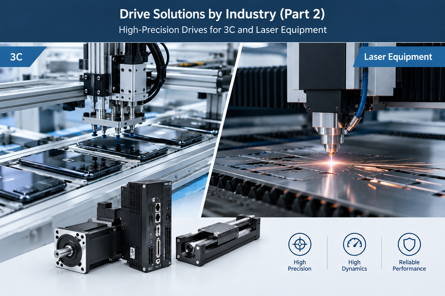
| Typical Workstation | Load and Stroke Characteristics | Drive Recommendation | Key Considerations |
|---|---|---|---|
| 3C dispensing and screwdriving axes | Low inertia, high-frequency start-stop | Closed-loop stepper with moderate microstepping | Start-stop shock and bead smoothness |
| 3C pick-and-place and inspection platforms | Short stroke, high reciprocation frequency | Low-voltage DC supply, S-curve accel/decel | Preload and backlash determine repeatability |
| Laser marking focus axis | Short travel, resolution first | High-microstep open-loop or closed-loop stepper | Backlash and lead error require calibration compensation |
| Laser cutting and engraving worktables | Long stroke, continuous feed | Closed-loop stepper or low-voltage servo | Avoid resonance zones and power interference |
For troubleshooting, work in the order of “mechanical first, then electrical, then electromagnetic”: coupling and preload → current and microstep settings → pulse frequency and accel/decel method → grounding, shielding, and common-mode interference (laser high-voltage power supplies are a common noise source) → if performance is still short, consider upgrading to closed-loop or servo. Change one variable at a time and log the results for fast root-cause attribution.
Later installments in this series will keep breaking down drive solutions industry by industry. If you are upgrading workstations around lost-step prevention and low-speed smoothness, start with HFY DRIVE’s closed-loop stepper drivers—most 3C and laser equipment can be retrofitted with minimal changes to the frame and wiring.
FAQ
Q: Is a higher microstep setting always better?
A: No. Microstepping mainly improves resolution and low-speed smoothness; positioning accuracy is still constrained by the motor’s step angle error and the mechanical drivetrain. Excessively high microstepping pushes up the pulse frequency and burdens the controller—just leave one step of headroom above the process requirement.
Q: Evenly spaced stripes appear on laser-engraved surfaces—what should be checked first?
A: First estimate the vibration frequency using “stripe spacing ÷ feed speed” and compare it against the pulse frequency at the time. Then check the coupling and preload, the current setting, and the accel/decel method in turn; if necessary, swap in a closed-loop drive for comparison testing.
Q: For a short-stroke axis, should I choose an open-loop stepper, a closed-loop stepper, or a low-voltage servo?
A: With moderate resolution requirements and a tight budget, choose high-microstep open-loop; where no lost steps and low-speed smoothness are required, choose a closed-loop stepper; for high speeds, fast accel/decel, or long continuous running, choose a low-voltage servo.