
Drive Engineering Details, Part 1: Full Isolation Design for Harsh Field Environments
A drive that runs flawlessly in the lab starts losing steps, throwing false alarms, and suffering damaged interfaces the moment it reaches the field. The root cause usually lies in isolation, not in parameter tuning. In this session we break down where field interference comes from and how it travels, clarify what optocoupler isolation and power isolation each take care of, and give you a full-isolation checklist you can apply directly during product selection and wiring.
Where Field Interference Comes From: Three Typical Paths
Many faults that only show up on site are rooted in an electrical environment far more complex than a test bench. Interference typically enters the drive along three paths:
- Conduction: contactor switching, relay coil kickback, and the start/stop of heavy loads superimpose microsecond- to millisecond-scale voltage spikes on the power and ground lines;
- Field coupling: the high-speed PWM switching of the drive’s own power stage couples noise into the control lines through the parasitic capacitance and mutual inductance between the motor cable and adjacent cables;
- Ground potential difference: grounding points in different cabinets or areas often sit several volts apart; once both ends share a ground, ground loop currents flow.
A quick order-of-magnitude estimate makes this tangible: for a 48 V bus drive, take the switching dV/dt of the power transistors as roughly 1 V/ns and the parasitic capacitance of the motor cable to ground as about 100 pF/m, or roughly 2,000 pF over a 20 m run. Each switching instant then drives a common-mode current peak of about I = C·dV/dt ≈ 2 A through the cable. With no low-impedance return path, these currents take ‘shortcuts’ along the signal grounds and shields: at best causing communication frame errors and lost pulses, at worst burning out interfaces. The shared ground line is precisely the shortcut most often taken.
Optocoupler Isolation: The Insulating Gate on the Signal Side
Optocoupler isolation addresses the signal layer. It follows an electrical-to-optical-to-electrical path: a light-emitting device on the input side converts current into light, and a photodetector on the output side converts the light back into current. Between the two sides there is only an optical path and no electrical connection. The grounds of the host controller and the drive therefore stay independent, and a ground potential difference cannot drive current along the pulse lines.
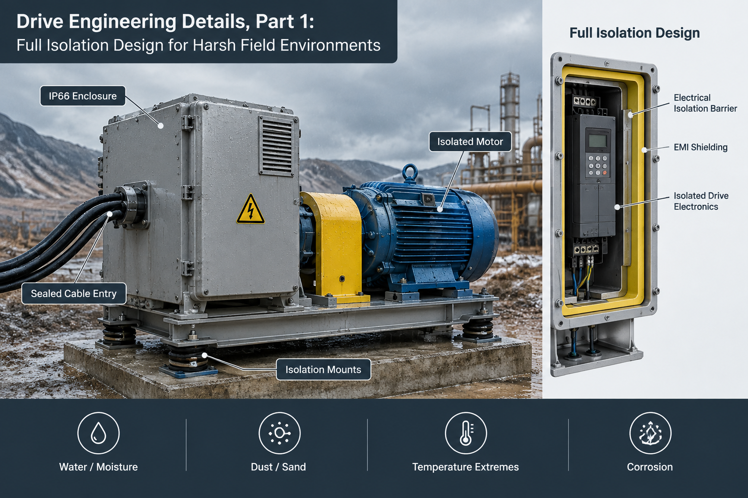
Three engineering points are worth noting:
- Isolation voltage is a short-term withstand value: common optocouplers are rated in the thousands of volts RMS, which reflects dielectric strength; it is not a voltage they can carry continuously;
- Delay and speed: optocouplers have turn-on and turn-off delays; high-speed pulse applications call for high-speed types, otherwise pulse edges are slowed and the maximum response frequency is limited;
- CTR degrades with age: the current transfer ratio falls with temperature and years of service; the input current-limiting resistor should leave margin so that signals do not weaken and error rates climb after a few years.
In one sentence: an optocoupler blocks the interference arriving over the signal lines, but does nothing about the portion coming in through power and ground.
Power Isolation: Without It, Full Isolation Is Only Half Done
Optocouplers stop the control signals, but the drive’s internal control circuitry still needs power. If the control supply shares a winding and a ground with the power stage, interference still pours in through the power ‘back door,’ and the isolation at the front end is wasted.
Two practices are common. First, insert an isolated DC-DC converter or a separate transformer winding between the control supply and the power supply so that the two sides become independent power domains. Second, partition the layout into power ground, control ground, and shield ground, tying them together only at a planned single point so that interference currents never cross sensitive circuits. From this we can distill three questions for judging ‘true full isolation’: are all signal ports isolated; do the control supply and the power supply belong to independent power domains; are the grounds of the individual domains kept separate and joined only at the designed single point? Full isolation holds only when all three answers are yes; if any answer is no, interference still has a path through.
The Engineering Case for Full Isolation: Comparison Table and Checklist
Full isolation is not about piling on components blindly; it is about being explicit about which currents are allowed to flow where. The trade-offs among the three approaches are shown below:
| Approach | Signal isolation | Power & ground isolation | Typical applications |
|---|---|---|---|
| Common-ground direct connection | None | None | Same cabinet, single supply, clean environment |
| Signal isolation only | Yes | None | Interference coupled mainly through signal lines |
| Full isolation | Yes | Yes | Long cable runs, multiple cabinets sharing a ground, mixed power and control wiring |
The payoff of full isolation does not appear on a datasheet. It turns ‘occasional and hard to reproduce’ problems into a design property of ‘does not happen’: interfaces no longer burn out from common-ground potential differences, communications no longer suffer frame errors from ground loop currents, and commissioning no longer means hunting over and over for a ‘clean ground.’
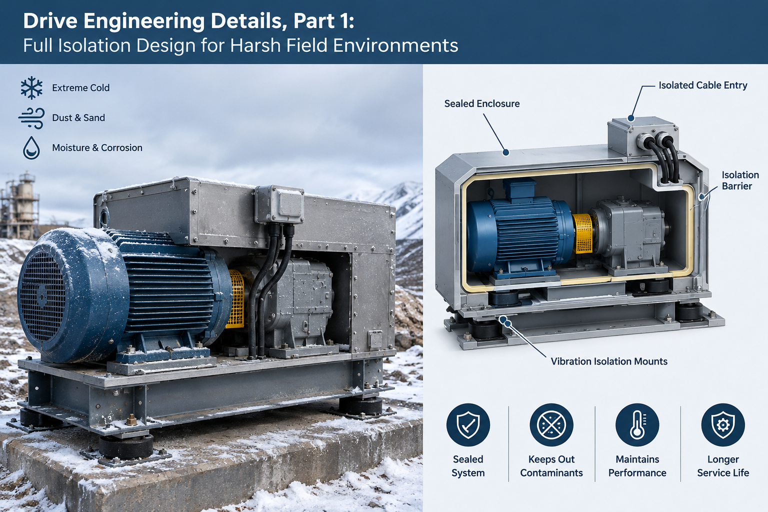
When selecting and wiring, check the following four items one by one:
- Are the pulse, direction, enable, and communication ports all isolated, and does the isolation voltage match the voltage levels on site;
- Do the control supply and the power supply come from mutually isolated power domains;
- Are the grounds of the isolated domains joined only at the designed single point, and is the shield grounding scheme clearly defined and actually implemented;
- Are signal cables routed in separate ducts from power cables, avoiding long parallel runs.
FAQ
Q: Does a 2500 V isolation rating mean it can withstand 2500 V continuously?
A: No. The isolation voltage generally describes dielectric strength under a short-term withstand test (for example, a one-minute test). The continuous working voltage should be far below that value and evaluated against the on-site voltage levels using creepage distance and clearance.
Q: I have chosen a fully isolated drive, yet occasional misoperation still occurs on site. In what order should I troubleshoot?
A: First run a common-ground comparison test: temporarily disconnect the signal ground; if the fault disappears, a hidden shared ground exists. Then check in turn whether peripheral circuits have bridged across the isolated grounds, whether shield grounding is consistent, whether power and signal cables are routed in separate ducts, and whether grounding is single-point. Isolation cannot close the gaps left by wiring and grounding workmanship.
Q: Full isolation adds cost. In which situations can it be relaxed?
A: With same-cabinet installation, a single supply, short cables, and a clean environment, a common-ground scheme is usually reliable enough. Once long cable runs, multiple cabinets sharing a ground, or mixed power and control wiring come into play, the reliability gains of full isolation typically far exceed its incremental cost.
Conclusion and Next Session
The essence of full isolation is to leave interference currents on the signal, power, and ground paths with nowhere to go. Later sessions in this series will cover input interfaces, thermal management, grounding, and other engineering details, starting next time with the electrical specifications and filtering of the pulse, direction, and enable signals. At the selection stage, you can begin by exploring HFY DRIVE’s closed-loop stepper drivers, whose input and power isolation design implements exactly the approach covered in this session.