
Industry Drive Solutions (Part 1): Multi-Axis Drives for Textile & Packaging Machinery
Textile and packaging machinery are typical multi-axis-intensive systems: yarn feeding, drafting, cutting, and cross sealing are chained together, and if any axis fails to keep up, the next station amplifies the error into cycle-time loss across the whole line. Built around two main themes—multi-axis motion coordination and high-frequency start-stop duty—this article provides a practical, ready-to-apply sizing framework for multi-axis drive configuration.
The Essence of Multi-Axis Coordination: Master-Slave Following and Phase Alignment
Unlike single-axis point-to-point positioning, most axes in textile and packaging equipment are tied together by electronic gearing or electronic camming: the master shaft—or a virtual master axis in the controller—outputs the phase, and the slave axes follow it in real time at a fixed ratio or along a cam table. On a flow wrapper, the film feed, cross-seal, and cutter axes must stay locked to the registration-mark phase; on a warp knitting machine, the loop-forming main shaft and the warp let-off shaft must hold a constant let-off ratio. The essence of synchronization is phase agreement—not each axis positioning accurately on its own.
Three drive requirements follow from this. First, inter-axis following error must be small: the drive’s position loop bandwidth and command latency directly determine phase lag. Second, no lost steps and no overshoot during dynamic motion, or seal-and-cut misalignment turns straight into scrap. Third, phase recovery after a material break or emergency stop, which requires the drive to support registration-mark homing or home-position offset. These three points also serve as the evaluation criteria for the drive selection comparison later in this article.
Start-Stop Frequency: A Tougher Test Than Rated Speed
Many engineers size motors by rated speed alone, but for winding and reciprocating stations, start-stop frequency is the first criterion. The cross-seal axis of a packaging machine reciprocates dozens to over a hundred times per minute with bag speed, and a reciprocating yarn-feed mechanism jogs hundreds of times per minute—meaning the windings and power devices undergo thousands of current transients every minute. On the motor side, copper losses and iron losses accumulate cycle after cycle; on the drive side, switching losses and braking energy deliver repeated shocks.
The consequences concentrate in three areas. Heating—the common industry reference is Class F insulation with a temperature-rise limit of about 105 K by the resistance method; if high-frequency start-stop keeps temperature rise close to that limit over the long run, reduce the current or move up to a larger frame. Torque collapse—the output torque of an open-loop stepper falls off quickly in the mid-to-high speed range, and if the torque is not there during acceleration, the motor loses steps. DC bus pump-up—frequent braking pumps energy back into the bus, and insufficient absorption capability trips an overvoltage alarm. Suggested troubleshooting order: measure the stabilized temperature rise first, then check following error under load disturbance, and finally inspect the braking circuit and bus voltage.
Recommended Configuration Approach: Set the Role First, Then the Motor Type and Bus
We suggest working down three layers—axis role, start-stop frequency, and synchronization requirements:
- Sort out master and slave: choose a master solution with high bandwidth that can output divided encoder pulses or a virtual master; configure the electronic gear ratio or cam table for each slave according to its following relationship—get the ratio right first, then refine dynamic accuracy.
- Choose the motor type by duty frequency and inertia: for low-frequency, high-inertia stations, low-voltage servos are the first choice; for high-frequency, small-to-medium-inertia reciprocating stations, closed-loop steppers come first—encoder feedback can raise an alarm and compensate before steps are lost, which handles frequent start-stop duty far better than open loop.
- Choose the bus by synchronization accuracy: with few axes and low cycle rates, a combination of pulse control plus RS485 parameter tuning is enough; where inter-axis phase tolerance is tight and whole-line coordination is required, choose CANopen or EtherCAT and align the command cycles of all axes with sync frames or distributed clocks.
Here is how the three common configurations compare:
| Configuration | Inter-Axis Synchronization Method | Typical Stations | Wiring and Commissioning Notes |
|---|---|---|---|
| Pulse-type closed-loop stepper | Controller distributes pulse timing to all axes | Few-axis, medium/low-speed film feed and yarn feed | Simple wiring; the synchronization ceiling depends on the controller’s processing cycle |
| CANopen bus drive | Alignment via SYNC frames | Loop-forming and feed coordination within a dozen or so axes | Use twisted-pair shielded bus cable; watch termination resistors and baud rate planning |
| EtherCAT bus drive | Distributed clocks, low synchronization jitter | High-speed cross sealing, multi-axis electronic camming | Pay attention to topology and consistent cycle times across all slaves |
Two rules of thumb: when slave-axis following error consumes more than half of the process tolerance, it is time to move from a pulse scheme to a fieldbus; when high-frequency start-stop keeps temperature rise pressing against the limit, it is time to move from open loop to closed loop or a low-voltage servo.
A Reusable Four-Step Sizing Method: Cross-Seal Swing Arm Example
Take a cross-seal swing arm (direct drive) that actuates 40 times per minute and walk through the sizing process:
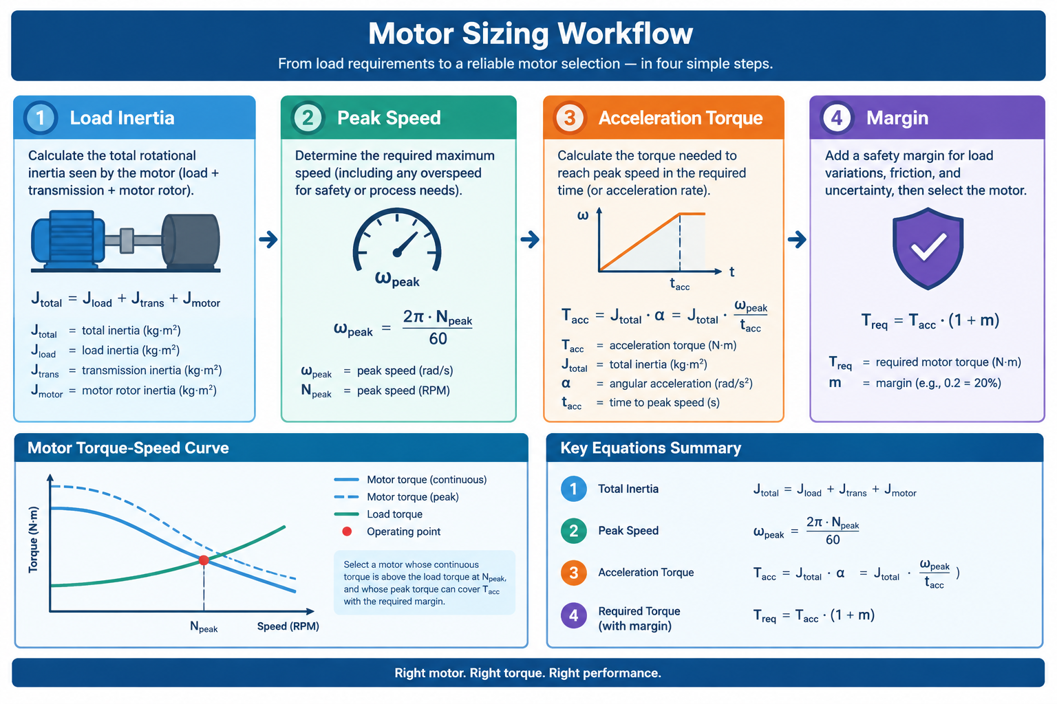
- Reflected inertia: the swing arm load reflected to the motor shaft is about 0.06 kg·m²; taking a typical rotor inertia of 0.008 kg·m² for this frame size, the inertia ratio is about 8:1—within the acceptable range for a closed-loop stepper.
- Back-calculate peak speed: the swing angle is 120° (about 2.1 rad) and each motion segment is about 0.5 s; with a triangular velocity profile, the peak angular velocity is about 2 × 2.1 ÷ 0.5 = 8.4 rad/s, or roughly 80 rpm—comfortably inside a stepper motor’s sweet spot.
- Acceleration torque: the acceleration phase lasts about 0.25 s with an angular acceleration of about 34 rad/s², giving acceleration torque of about 0.068 kg·m² × 34 rad/s² ≈ 2.3 N·m, plus roughly 0.4 N·m of friction and sealing/cutting process resistance.
- Select a size with margin: peak torque is about 2.7 N·m; with a 1.5× margin, choose a frame with a holding torque of 4 N·m or more, and verify that the drive’s available torque curve still leaves headroom around 80 rpm.
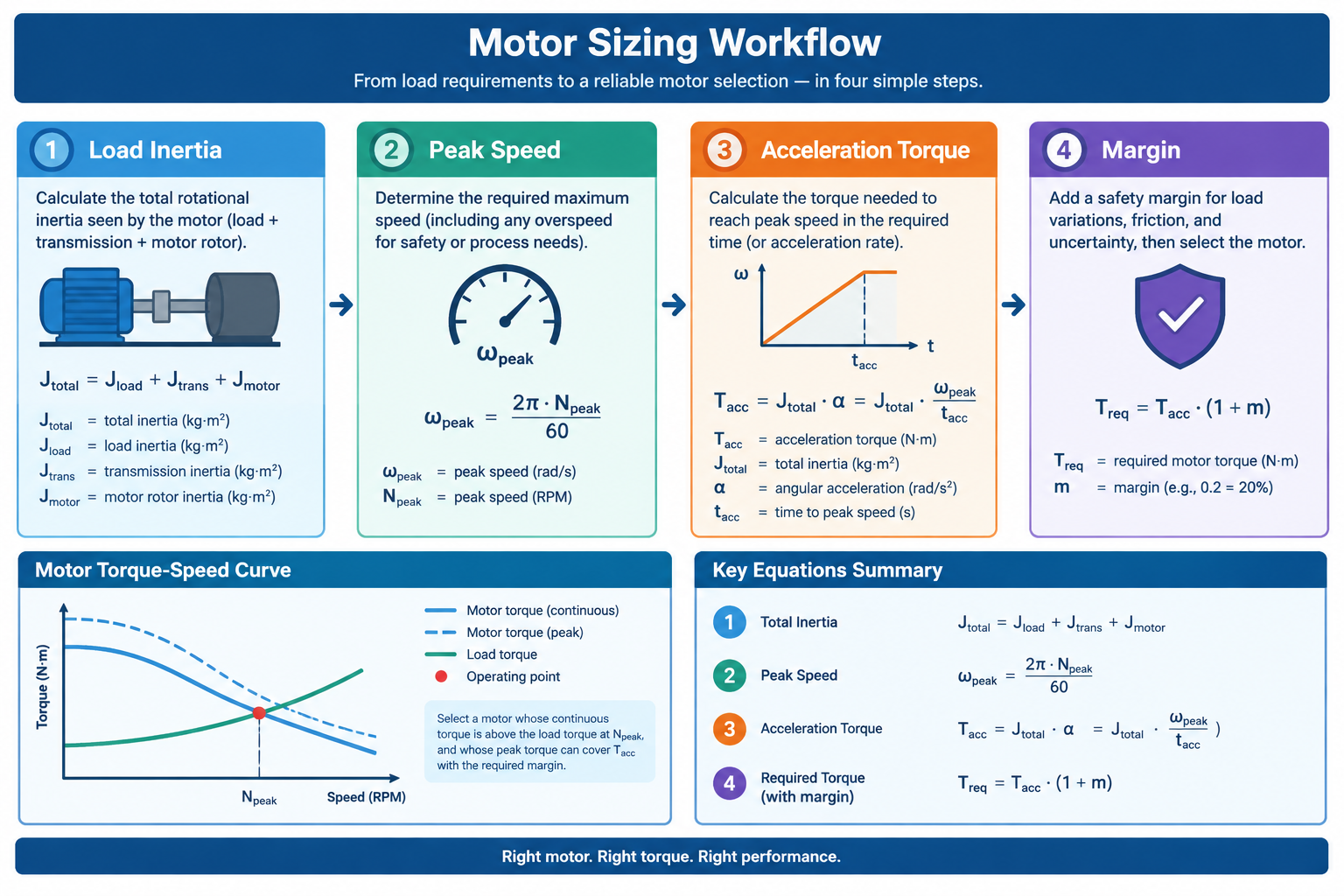
This four-step method—inertia ratio → peak speed → acceleration torque → margin—applies equally to yarn-feed, web-guiding, and film-feed axes: put the cycle of every station on the line into a table and go through it axis by axis, then return to the previous section to re-check the synchronization scheme after the first pass. Sizing is never a one-shot calculation; it is an iterative loop between motor type and bus scheme.
Frequently Asked Questions
Q: Is EtherCAT a must for multi-axis coordination?
A: No. With few axes, low cycle rates, and loose phase tolerances, pulse-type closed-loop steppers are entirely adequate. The advantages of CANopen/EtherCAT in synchronization accuracy and wiring and maintenance only truly pay off once following error starts eating into process tolerance, or when many axes have to move as one line.
Q: The motor runs hot under high-frequency start-stop—how do I tell whether it exceeds the limit?
A: First check against the temperature-rise limit of the insulation class—about 105 K by the resistance method for Class F; a spot thermometer reading of the housing is a useful auxiliary check. If the stabilized temperature rise keeps approaching the limit, check the drive’s idle-current reduction setting and whether the run current is set too high, then consider a larger frame or a low-voltage servo.
Q: Can a closed-loop stepper still lose steps?
A: Encoder-based closed loop can raise an alarm or automatically catch up the instant steps are lost, which sharply reduces the probability—but it does not change the torque limit. Sudden load changes or overly aggressive acceleration/deceleration can still trigger a position error alarm. Frequent alarms are a sign that the sizing is too tight: go back to the four-step method and recheck the inertia ratio and torque margin.
Summary and a Look Ahead
Three takeaways from this article: synchronization is, at its core, phase agreement; start-stop frequency decides the motor class; size the torque with the four-step method, then go back and settle the bus. Take these three points back to the production line, and most multi-axis configuration debates will converge quickly.
More installments of this Industry Drive Solutions series are on the way, covering multi-axis configurations for machine-tool loading/unloading, logistics sorting, and other scenarios. If you want to lock down the textile and packaging stations first, start filtering by frame size and bus type on our closed-loop stepper drivers category page.