Custom Driver Board Development Process: Requirements Evaluation and Solution Design
Every custom driver board project runs into the same pain point: the costliest part is usually not the design fee, but requirement churn and prototype rework. What follows — a six-category requirements input checklist, a torque estimation framework, and a pre-prototyping review checklist — can be applied directly to your own project.
1. Requirements Input Checklist: Translating “I Need a Driver Board” into Engineering Language
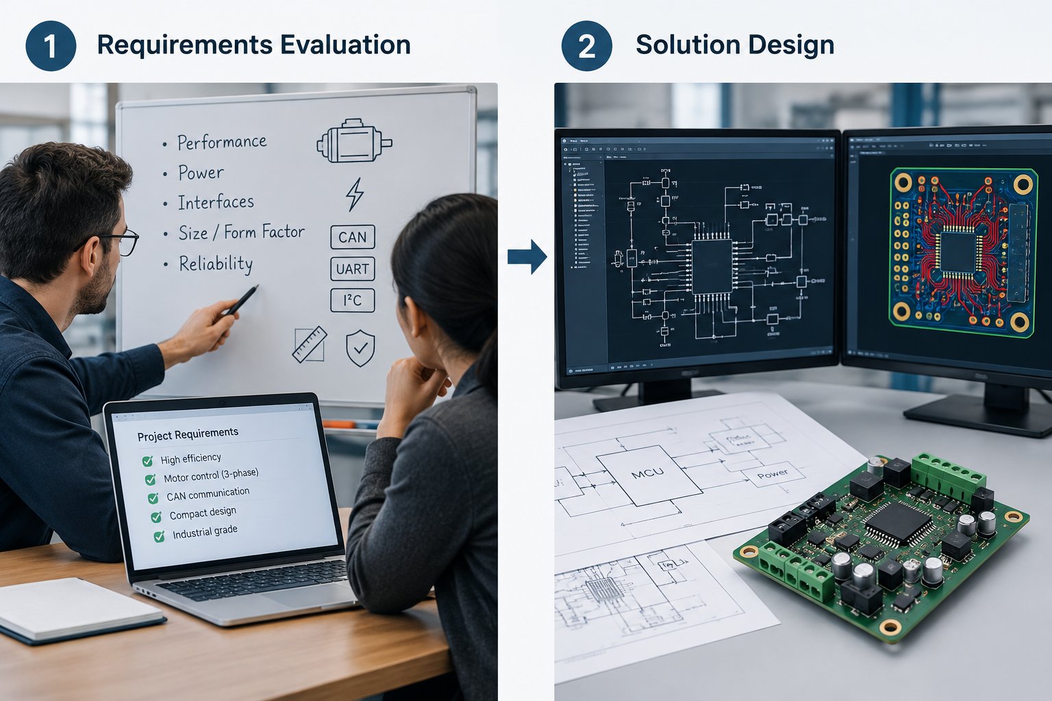
A lot of projects kick off with a single sentence: “Build me a driver board that can run a motor.” To whoever has to design it, that sentence carries virtually zero information. Every key parameter of the board, from power-stage current and bus voltage to the control interface and the protection logic, is derived backward from the load and the operating conditions. How fast the design converges depends directly on how complete your requirements input is.
Before the kickoff meeting, organize the following six categories into a table and hand it to the design team:
- Load and motion: load type (lead screw, belt, or direct drive), inertia reflected to the motor shaft, target speed, acceleration/deceleration times, positioning accuracy, and start-stop cycle rate;
- Power supply: available voltage levels (e.g., DC 24 V/48 V, AC 220 V), power headroom, and whether multiple axes share a common bus;
- Control interface: pulse + direction, analog, or a fieldbus such as EtherCAT, CANopen, or RS485, plus the host controller platform;
- Environment and mounting: ambient temperature, dust, vibration, cooling conditions, board outline, and mounting method;
- Volume and lifecycle: number of prototypes, expected annual volume, and required years of supply, which together determine the component sourcing strategy;
- Special requirements: IP rating, certification needs, debug interfaces, and DIP switch and indicator conventions.
The item most often overlooked is the motion profile. Say only “it drives a lead screw” without giving travel and cycle period, and there is no way to compute the required speed and torque. The design then gets revised over and over on guesswork.
2. Quantifying the Load: A Reusable Torque Estimation Framework
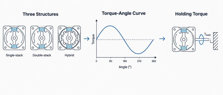
Driver board selection is derived backward from the motor, and motor selection from torque. In stepper applications, the total torque requirement ≈ friction (including lifting) torque + inertia × angular acceleration. A worked example: lifting a 5 kg load with a 5 mm lead screw gives a lifting torque T = mg × P/(2πη); at an efficiency of 0.9 that comes to about 0.043 N·m. Accelerate the load from standstill to 300 rpm within 0.1 s and the angular acceleration is roughly 314 rad/s², with the reflected load inertia J = m(P/2π)² ≈ 3×10⁻⁶ kg·m². Add the screw and rotor inertias and the acceleration torque is on the order of 10⁻³ N·m. The total comes to about 0.05 N·m. Applying a 30%–50% margin points to a small-frame motor with a holding torque of 0.1–0.2 N·m, which typically corresponds to a rated phase current in the 1–2 A range.
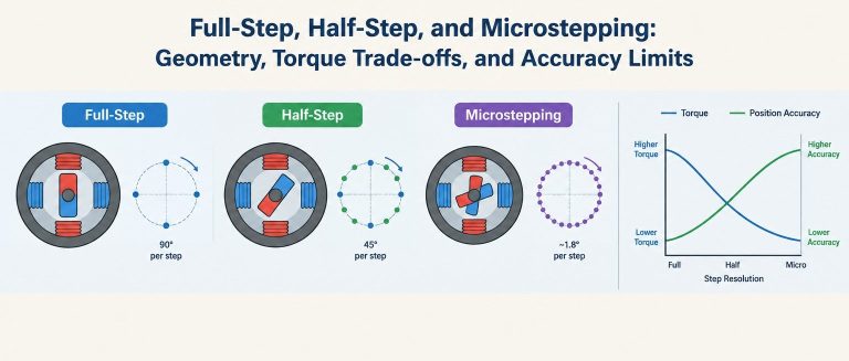
Once the motor is set, two core parameters of the driver board follow. The phase current determines the power switch ratings and the sense resistors, while the bus voltage sets the mid- and high-speed torque plateau. Stepper motor torque falls off as speed rises because winding inductance limits how fast current can build. Raising the bus voltage from 24 V to 48 V is one of the most direct ways to improve high-speed torque, though voltage margin and thermal design requirements rise in step.
Write this estimation chain into your requirements document, and every later design discussion has a common anchor. It also puts an end to the “it doesn’t feel fast enough, so swap in a bigger motor” loop.
3. Solution Design: Trade-offs Across Topology, Control, and Protection
For the power topology, the usual choices are an integrated gate driver plus discrete MOSFETs or an intelligent power module (IPM). The gate driver route is flexible and allows individual component replacement, which suits low-to-medium currents. The IPM is highly integrated and simplifies thermal and protection design, but after a failure it is typically replaced as a whole. Either way, the current rating should be sized at the peak phase current plus at least 30% margin; that is standard engineering practice.
The control approach depends on cycle rate and axis count. A single axis with relaxed timing can use an open-loop pulse drive. If step loss and smoothness matter, move up to encoder-based closed loop. Multi-axis coordination with centralized diagnostics calls for a fieldbus. The trade-offs are summarized below:
| Approach | Typical Applications | Advantages | Key Considerations |
|---|---|---|---|
| Open-loop pulse | Single axis, stable load | Low cost, simple commissioning | Prone to step loss at high speed; leave ample torque margin |
| Encoder closed loop | Medium-to-high cycle rates, step-loss sensitive | Step-loss alarm, smooth running | Slightly higher cost; gain tuning required |
| Fieldbus (EtherCAT/CANopen/RS485) | Multi-axis coordination, centralized control | Less wiring, rich diagnostics | Master capability and protocol stack cost must be assessed |
Protection and thermal design cannot be patched up afterwards. When a stepper motor decelerates or emergency-stops, it pumps energy back into the bus and raises the bus voltage, so the buffer capacitor or bleeder circuit must be settled at the design stage. Define the overcurrent and over-temperature thresholds here as well, long before anything burns out.
4. Pre-Prototype Review: Using a Checklist to Stop Trouble Early
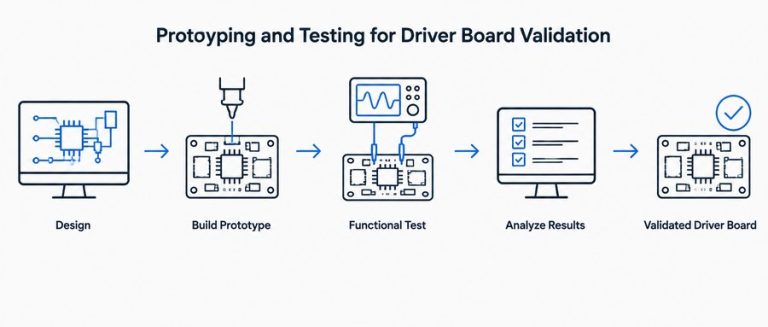
The purpose of this review is to freeze the requirements baseline. Walk through the checklist item by item in the order electrical-thermal-interface-manufacturability:
- Electrical: Is the power switch voltage rating margin adequate (commonly specified at 1.5–2× the bus voltage)? Is the discharge path for bus pump-up voltage complete? Does the overcurrent sensing cover the worst-case condition?
- Thermal: Estimate total losses from conduction and switching, then verify the heat-removal path against temperature-rise targets. Derating power device junction temperature to no more than 100–125 °C is common practice;
- Interface: Connector keying, noise immunity of pulse inputs (differential or optocoupler), grounding and shielding scheme, and whether debug and firmware upgrade ports are reserved;
- Manufacturability: Are second sources available for critical components? Does the BOM contain end-of-life risk parts? Do test points support fast production-line testing?
The review passes when three documents are complete: a frozen requirements specification, a version-controlled schematic and BOM, and a test plan with clearly assigned owners. From then on, any change goes through a formal change process and the test plan is updated in sync. In practice, this discipline saves more schedule time than any individual technical check.
Conclusion
Requirements evaluation and solution design largely decide whether a custom project succeeds, and they deserve far more discussion time than most teams give them. Three reusable deliverables come out of this article: the six-category requirements input checklist, the torque-voltage estimation chain, and the electrical-thermal-interface-manufacturability review checklist.
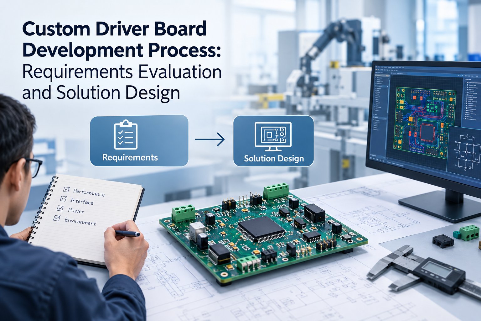
▲ Knowledge map of this article
And if you want to compare your plan against the parameter framework of mature products, browse our closed-loop stepper drivers category.