
Closed-Loop Integrated Motors (3): Commissioning Checklist from Prototype to Production
A closed-loop integrated solution that runs smoothly on the prototype often ends up “behaving differently from unit to unit” in small batches. The problem usually lies in the handover between commissioning and consistency control. Continuing the engineering perspective of the previous installment, this article provides an actionable commissioning checklist—five-step auto-tuning, batch consistency control, pre-production verification, and on-site troubleshooting—so prototype results can be replicated stably in mass production.
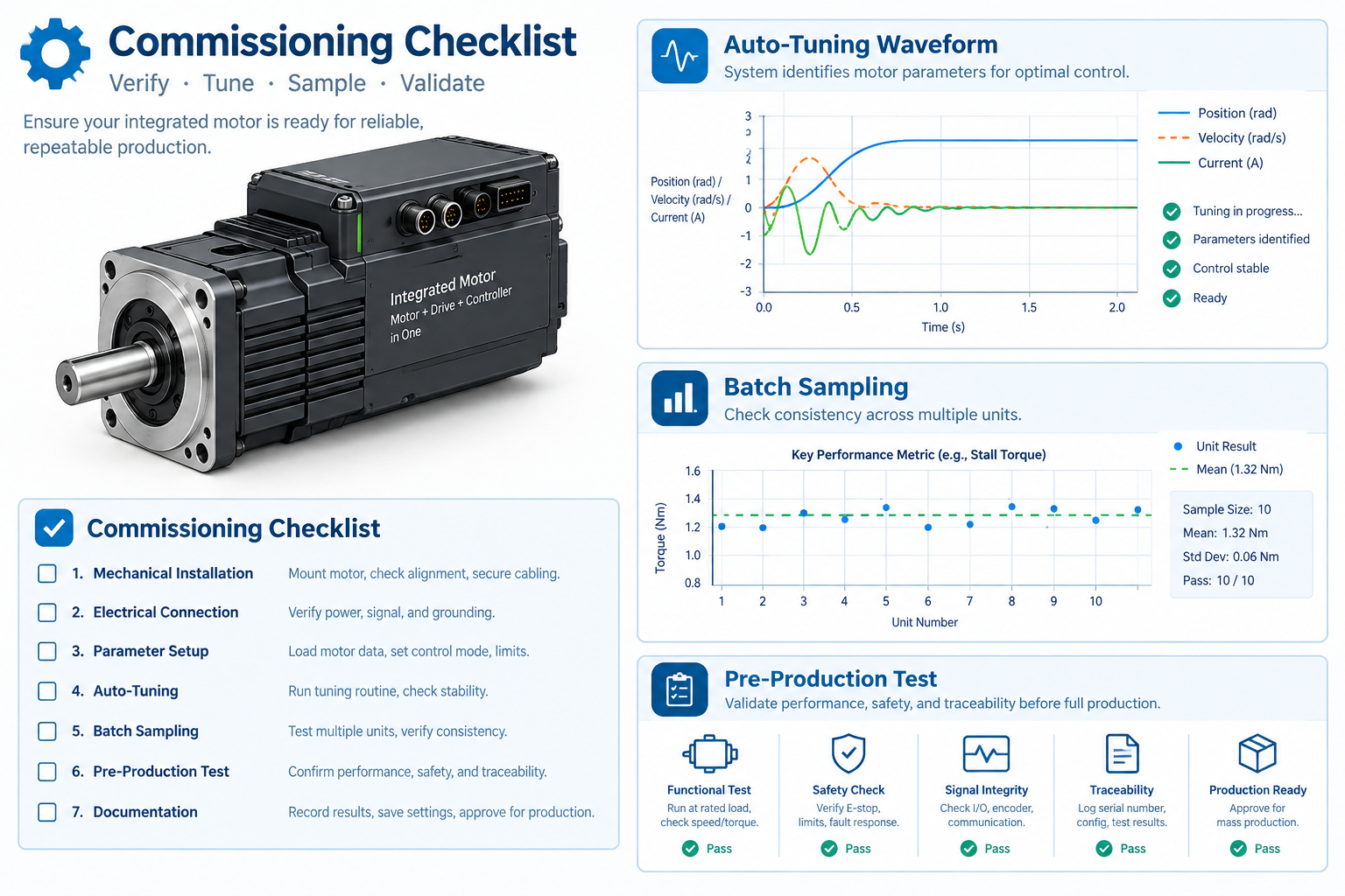
Auto-Tuning Procedure: Five Steps to Establish the Production Baseline
The previous installment analyzed the benefits a built-in driver brings to machine structure and wiring. Before that account carries over into mass production, however, there is still the commissioning process to get through. The starting point for any closed-loop integrated solution is a properly executed auto-tune on the prototype—it becomes the baseline for everything that follows. One reminder: the tuning result is a baseline, not an inspection exemption. We recommend the following five steps:
- No-load tuning: Confirm electrical parameters and base gains; check that the in-position signal and current waveforms are clean;
- Loaded tuning: Re-tune with the real load and transmission mechanism connected, and record the differences from the no-load result;
- Operating-condition review: Fine-tune stiffness, filtering, and acceleration/deceleration at the extremes—maximum speed, heaviest load, shortest cycle time;
- Fault injection: Deliberately induce stall and sudden load steps to verify that protective and alarm responses behave as expected;
- Parameter freeze: Export and archive the final parameters under version control as the mass-production template.
At every step, leave a written trail: tuning date, firmware version, ambient temperature, and the tuned resistance, inductance, and gain values. These records may seem tedious when commissioning a single unit, but once a production machine behaves differently from the prototype, they are the first-hand evidence for deciding “parameter issue or incoming-material issue.” A large gap between no-load and loaded tuning results usually points to transmission backlash, coupling compliance, or an inertia ratio beyond the original estimate—re-check at the mechanical level rather than forcing it down with gain.
Behind the Tuning Result: What Auto-Tuning Actually Identifies
Many engineers treat auto-tuning as “one-click magic,” but to make the result reproducible you need a rough idea of what it does: the drive first injects excitation signals to identify winding resistance and inductance and tunes the current loop; it then uses encoder feedback to estimate load inertia and damping, and derives recommended gains for the velocity and position loops. The tuning result reflects the combined state of “this motor + this transmission + the temperature at that moment”—change any one of them and the result may drift.
A few lessons follow: winding resistance changes noticeably with temperature, and gains tuned on a cold machine may differ from a warm one, so the production baseline should be established at a temperature close to actual operating conditions; the load inertia ratio is a hard constraint on the gain ceiling, so to raise stiffness further, check the reduction ratio and coupling stiffness first instead of increasing gain; filtering suppresses ripple but introduces phase lag, so it must be weighed against cycle-time requirements.
One more often-overlooked variable: on a low-voltage DC supply, the bus voltage level (e.g., 24V or 48V) determines the torque margin in the high-speed range. On sites where long cables cause noticeable voltage drop, oscillation can occur even with the same gain template—the production template should spell out the supply conditions.
Batch Consistency: From Tuning One Unit to Controlling a Whole Batch
The root cause of consistency problems is usually not the parameters themselves but variation in incoming materials and process; the idea is to replace the prototype-stage “tuning” with production-stage “controlling”:
| Dimension | Prototype Stage | Production Stage |
|---|---|---|
| Parameter source | Per-unit auto-tuning | Unified template + sampling re-verification |
| Motor–drive pairing | Random matching | Motors and drives from the same batch paired preferentially |
| Software version | Ad-hoc updates | Firmware and parameter versions locked under change control |
| Verification depth | Full-scope screening | Sample testing of key items + periodic full inspection |
One addition: winding and magnet characteristics of motors from different batches differ within reasonable limits; after a batch change, sample re-verify the tuning results, and if the deviation is significant, update the template instead of forcing the old values onto the new batch.
How large a deviation counts as “significant” should be agreed in advance: for example, compare the deviation of tuned gains from the template values, the in-position time, and the temperature rise at rated load against the template records; anything outside the preset range triggers re-verification, avoiding unit-by-unit judgment by feel.
Recommended Pre-Production Verification Items
The items below are listed by priority, and most can be completed right at the assembly station:
- Temperature rise and insulation: Run continuously at rated load until thermal steady state, keeping temperature rise within the customary limits for the selected insulation class (e.g., Class B or Class F);
- Extreme motion: Cycle for extended periods at maximum speed and maximum acceleration/deceleration, confirming no step loss and no overcurrent;
- Protective functions: Trigger stall, overload, overvoltage, and undervoltage protections one by one to verify alarm outputs and shutdown behavior;
- Fieldbus communication: After networking via CANopen, EtherCAT, or RS485, run coordinated multi-axis motion and interference tests, confirming reconnection after dropouts and synchronization performance;
- Environmental suitability: Re-check vibration, dust, and low-temperature starting against actual conditions, and run burn-in tests on samples where necessary.
For acceptance criteria, common industry practice offers useful reference points: Class B insulation corresponds to roughly 130°C and Class F to about 155°C of heat resistance, and actual testing should still leave margin within those limits; for fieldbus verification, start with a single axis, then network the axes—step up the load gradually and confirm that in-position signal timing stays unchanged; for environmental items that cannot be tested on site, sample-based burn-in can serve as alternative verification.
Field Troubleshooting Paths for Common Faults
Completing the checklist is not a once-and-for-all fix; three fault types recur frequently in the field, and each should be followed along a fixed path. Occasional step-loss or position-error alarms: first look at where they occur—if they cluster in high-speed and hard accel/decel segments, check supply voltage margin and the accel/decel profile first, then mechanical binding and coupling slip; if they cluster at workstations with long cables or strong interference, turn to shielding, grounding, and bus termination.
Excessive temperature rise: first determine whether the heat source is the motor or the drive, using a thermometer on the end bell and the housing separately. On the motor side, common causes are a current set too high or unnoticed prolonged stalls in the duty cycle; on the drive side, it is usually heat dissipation at the mounting surface or ventilation clearance. Locate the heat source first, then decide whether to adjust current, change the cycle, or modify the cooling structure—do not reverse that order.
The same template behaving differently across stations: prioritize the variables shared between stations—supply voltage and cable length, grounding method, and drivetrain alignment—then record these station differences in the applicability notes of the parameter template; that is far more controllable than tweaking each unit after the fact.
FAQ
Q: Can parameters still be adjusted manually after auto-tuning?
A: Yes. Auto-tuning provides the baseline; for special loads or noise requirements you can fine-tune gains and filtering on top of it, but every change must be recorded and synced into the parameter template.
Q: Do I need to re-tune after switching to a new motor batch?
A: Sample re-verification is recommended. Characteristics vary reasonably between batches; if tuning results deviate significantly from the template, update the template rather than reusing old parameters.
Q: Which production sampling checks offer the best return?
A: Prioritize three items—no-load tuning consistency, temperature rise at rated load, and no step loss at maximum speed. They take little time and expose batch problems most effectively.
Previous Installments
The commissioning map from prototype to mass production does not end here; upcoming installments of this series will continue to break down hands-on topics in selection and integration. Before you start selecting hardware, browse the closed-loop stepper drives category page. Previous installments: