Full-Step, Half-Step, and Microstepping: Geometry, Torque Trade-offs, and Accuracy Limits
Full-step, half-step, and microstep—the three options sit on nearly every stepper drive panel, and many engineers set them every day without being able to say exactly how the three modes differ, let alone whether microstepping actually buys more accuracy. Starting from the resultant MMF of the two phase currents, this article explains the geometry behind all three modes, their torque costs, and the true boundaries of accuracy in one pass—so you can match the right mode to your application right away.
One Premise: The Rotor Only Follows the Resultant MMF Vector
A two-phase stepper motor has two sets of windings, A and B, on its stator. Energizing a winding produces an MMF (magnetomotive force)—think of it as the magnetic pull that turns the rotor: directed along the winding axis, with a magnitude proportional to the current. The two MMFs add as vectors to form a single resultant MMF vector.
Whether the drive is set to full-step, half-step, or microstepping, the rotor simply chases this resultant vector. The entire difference between the three modes lies in how that vector is made to step forward.
Full-Step and Half-Step: The Number of States Sets the Step Angle
In full-step mode, both phase windings carry their full rated current at the same time and only the current direction is switched, leaving just four states per electrical cycle: A+B+ → A-B+ → A-B- → A+B-. The resultant vector jumps 90° (electrical angle) per step, and the rotor advances one full step angle. In a 1.8° motor the rotor tooth pitch is 7.2°; over one electrical cycle the rotor travels exactly one tooth pitch, so four full steps amount to 7.2° ÷ 4 = 1.8°.
Half-stepping inserts four single-phase states between the four two-phase states, making eight states in all. The vector now jumps 45° per step, halving the step angle to 0.9°. Resolution doubles—and the price tag comes with it.
On the single-phase steps, the MMF amplitude is only 1/√2 ≈ 0.71 of the two-phase state, and torque drops to roughly 0.71× as well. Torque alternates between strong and weak on consecutive steps, so rotor speed surges and slows in step—at low speed this is felt as a perceptible jerkiness. That is the torque ripple of half-stepping.
Microstepping: Replacing the Square Wave with a Sine Wave
Microstepping abandons on/off switching altogether: the two phase currents vary continuously as Ia = I·cosθ and Ib = I·sinθ, where I is the phase-current amplitude and θ is an electrical angle that increases with time. The resultant vector keeps a constant amplitude of I while its direction rotates uniformly with θ, and the rotor turns right along with the vector.
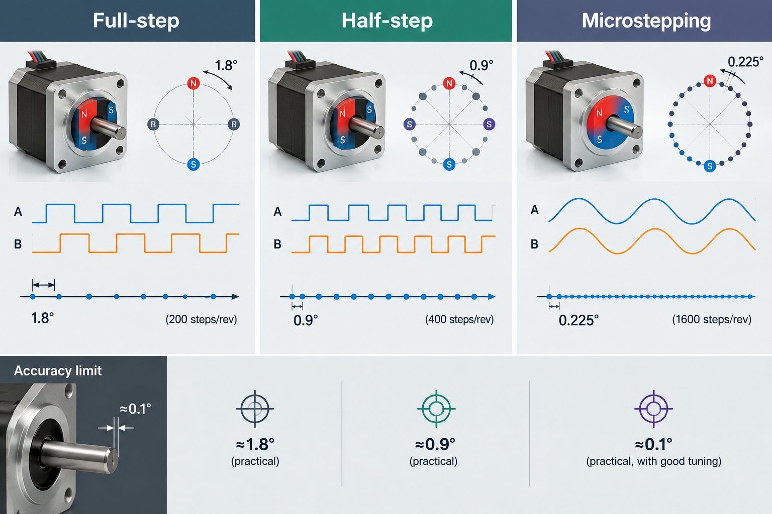
“16 microsteps” means dividing one full-step angle into 16 increments—for a 1.8° motor, 0.1125° per increment; at 256 microsteps it is nominally just 0.007°. The higher the division rate, the closer the current waveform comes to a true sine wave, and the smaller the steps in between.
| Mode | Number of current states | Vector rotation per step | Torque behavior |
|---|---|---|---|
| Full-step | 4 | 90° | Maximum amplitude, strongest per-step torque |
| Half-step | 8 | 45° | Single-phase steps give about 0.71× the two-phase torque, with ripple |
| Microstep | Increases with the division rate | 90° ÷ division rate | Amplitude unchanged, restoring torque per step shrinks |
The Three Benefits of Microstepping
Some background first: stepper motors have a well-known weakness at low speed. With every step, the shock of the current transition makes the rotor ring back and forth a few times around its new equilibrium point. When the stepping rate approaches the rotor’s natural oscillation frequency, that oscillation is amplified step by step—at worst causing lost steps (the commands keep counting while the rotor falls behind) or even an audible squeal. This is low-frequency resonance, and most of microstepping’s benefits tie straight back to it.
- Smoother low-speed motion: less energy is injected into the system with each step, the resonance excitation is weakened, and the motor is less likely to start shaking in certain speed bands;
- Quieter operation: smaller current steps reduce ripple and electromagnetic noise, especially noticeable at low speeds;
- Finer theoretical resolution: the nominal step angle can be made very small, so control commands can be issued far more densely.
All three benefits are matters of dynamic quality—positioning accuracy is a different story entirely, and it gets its own discussion below.
The Two Hurdles That Keep Microstepping from Buying Accuracy
The first hurdle is the load angle. The rotor is dragged along by the resultant vector through the spring-like pull of the magnetic field. As long as there is any load torque on the shaft—even just friction—the rotor lags the vector by a load angle, and the heavier the load, the larger the lag.
The moment the load changes, the load angle changes with it—and so does the rotor’s actual angular error. The drive never measures rotor position, so it is completely blind to this.
The second hurdle is manufacturing tolerance. Machining errors in the rotor tooth pitch define the motor’s intrinsic accuracy; a no-load step-angle error of around ±5% is common in the industry, which for a 1.8° motor means ±0.09°. No matter how fine the microstepping, it cannot resolve below this intrinsic floor. When you see “256 microsteps” in the marketing, be clear about what it promises: smoothness. Accuracy still depends on the motor itself.
The Hidden Cost of Microstepping: Less Torque per Step
Microstepping only switches the vector’s direction more finely; the amplitude is unchanged, so the motor’s maximum holding torque (the breakaway torque it can resist while energized) stays exactly the same. But the step angle is now smaller, so the restoring torque of a single microstep—the torque that pulls the rotor back to its new equilibrium point—peaks at about sin(90° ÷ division rate) of the maximum holding torque, roughly inversely proportional to the division rate. At 16 microsteps, that is only about one-tenth of the full-step value.
The higher the division rate, the smaller the load a single microstep can actually move. A familiar situation on the shop floor: friction runs high, microstepping is set very fine, and the rotor cannot keep up with each individual microstep, accumulating a small lag. Once the load grows large enough, whole steps are lost all the same.
Engineering Takeaway: Microstepping Buys Smoothness; Accuracy Comes from Outside
What microstepping buys is smoothness and quiet running, not accuracy. For equipment sensitive to noise and low-speed smoothness, set the division rate as high as you like; for high-speed, high-load duty, keep it moderate and leave that headroom to torque.
When accuracy is the priority, there are two routes. One is the mechanical drivetrain: use gear reduction or the lead of a screw to dilute the output displacement per step, incidentally multiplying the usable torque as well. The other is closed loop: an encoder measures the rotor position in real time, so both load-angle drift and lost steps can be compensated on the fly.
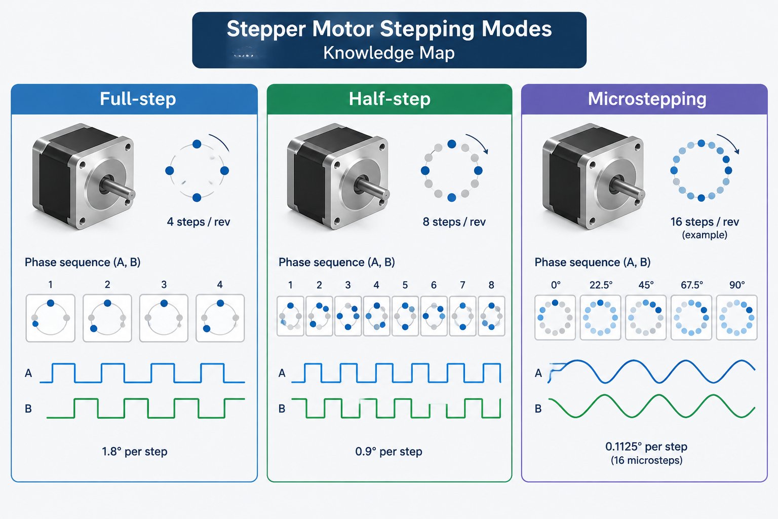
▲ Knowledge map of this article
To pull it all together: full-step is a hard switch among four states; half-step uses eight states but carries torque ripple; microstepping drives the phases with sine and cosine, buying smoothness, quiet, and nominal resolution—while the ceiling on accuracy is still set by the load angle and tooth-pitch tolerance. If your machine is torn between positioning reliability and noise, take a look at our closed-loop stepper drivers.